|
Frequently Asked Questions
Power Supplies
Aktakom Power Manager Express 3 cannot connect to APS-7205 power supply. What should I do?
What are common signs of overload or short circuit?
What do CV and CC mean?
What is the difference between a linear and a switching power supply?
What is a DC power supply?
What cooling system does it use?
Is the APS-3320 a linear or switching power supply?
What does "single-channel" mean?
What is the Aktakom APS-3320 DC Power Supply used for?
What kind of protection does the APS-7306 provide?
How do I switch between voltage and current adjustment?
Does the APS-7306 have memory or preset functions?
What is the APS-7306 power supply used for?
How to set the output voltage or current using the rotary encoder?
Why does my APS-7306L(LS) power supply not work with LAN cable connected?
I was told there is a video tutorial for this device, where can I see it?
Can I store voltage and current values in the device memory?
What operating modes does the APS-7306(L/LS) DC Programmable Power Supply have?
How do I connect the program software for APS-7306LS DC Programmable Power Supply?
What software should I download to work with the APS-7306LS DC Programmable Power Supply?
How to memorize the voltage and current values?
How to configure the program's interface window?
How to check power supply network settings?
How to connect to the sync input of AKTAKOM APS-3xxxLS and APS-7xxxLS power supplies with remote control?
Does the current parameters on AKTAKOM APS-7306 power supply display coincide with the readings of the program?
When I press “Remote” there is nothing happening to AKTAKOM APS-7306 power supply control. What is the reason?
What current protection do AKTAKOM power supplies use?
How to set parallel tracking mode when operating Aktakom ATH-22xx?
How to set series tracking mode when operating Aktakom ATH-22xx power supply?
What is the maximum current consumption of APS-3610 power supply at full load?
What instruction should I follow to work in the voltage stabilization mode?
How to work in the current stabilization mode?
How to connect Aktakom APS-3320L power supply to my PC?
How to connect to the power supply via web-interface?
Do AKTAKOM power supplies have short circuit protection?
May I use AKTAKOM power supplies to charge accumulators?
Can I ground one of “+” or “-” terminals when using AKTAKOM APS-1915 power supply?
How to set the timer delay parameters when using Rigol DP832A power supply?
How to set the timer delay parameters when using Rigol DP832 power supply?
How to set the timer parameters when operating Rigol DP832A power supply?
How to set the timer parameters when operating Rigol DP832 power supply?
How to work in Voltmeter mode of APS-7151 power supply?
How to work in Milliohmmeter mode of APS-7151 power supply?
How to activate remote measurement function of APS-7151 power supply?
Making OCP on and pressing output switch; and then the output is automatically shut off.
Output voltage rises slowly when output button is on. Why?
Pressing ON/OFF, there is no output when power on. Why?
The panel buttons don't work when power on. Why?
How to find MAC address of a power supply with LAN interface?
How to connect APS-7303L (APS-7305L) power supply to the program?
How to see a device serial number in AKTAKOM Power Manager software?
How to install the device driver for the operation via USB?
Can APS-3205 (APS-3203) power supply be used to supply the amplifiers on operational amplifiers?
How to change voltage and current values?
Aktakom Power Manager Express 3 cannot connect to APS-7205 power supply. What should I do? |
Set communication interface settings as described in user's manual. Do the following:
- Press SHIFT, then COMM button on the APS-7205 front panel to open communication interface settings window. Use knob to move the cursor to the corresponding place.
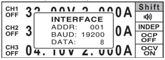
- Set ADDR to 001.
- Set BAUD to 19200.
- Set DATA to 8.
- Press ENTER button to save settings.
- Press POWER button to turn off the power supply, then turn it on again. Communication interface settings will be updated.
- Run Aktakom Power Manager Express 3 application again to detect APS-7205 power supply.
Up
|
What are common signs of overload or short circuit? |
-
Sudden switch from CV to CC mode
-
Output voltage drops
-
Protection indicator lights up
In such cases, disconnect the load and verify settings before continuing.
Up
|
What do CV and CC mean? |
-
CV (Constant Voltage): The voltage stays fixed, current varies with load.
-
CC (Constant Current): The current stays fixed, voltage changes to maintain that current.
The power supply automatically switches between these modes as load conditions change.
Up
|
What is the difference between a linear and a switching power supply? |
-
Linear power supply: Low noise, stable output, ideal for sensitive analog electronics.
-
Switching power supply: Smaller, lighter, more efficient, but produces higher noise.
Up
|
What is a DC power supply? |
|
A DC power supply converts AC input from the mains into a stable direct current (DC) output. It’s used to power electronic circuits, charge batteries, and perform testing or calibration in research and manufacturing environments.
Up
|
What cooling system does it use? |
The APS-3320 includes a smart cooling fan that automatically activates based on internal temperature, ensuring reliable long-term operation without excessive noise.
Up
|
Is the APS-3320 a linear or switching power supply? |
It is a linear regulated power supply, providing low output noise, fast transient response, and superior stability — ideal for sensitive analog and communication circuits.
Up
|
What does "single-channel" mean? |
A single-channel power supply provides one independently adjustable output.
The APS-3320 delivers one powerful output channel (30V / 20A) for high-current or high-power applications.
Up
|
What is the Aktakom APS-3320 DC Power Supply used for? |
|
The APS-3320 is a single-channel linear adjustable DC power supply designed for use in laboratories, production lines, testing, and repair environments.
It provides a precisely regulated output of 0–30V and 0–20A, suitable for powering and testing circuits, electronic components, and high-current devices.
Up
|
What kind of protection does the APS-7306 provide? |
The APS-7306 includes:
-
Over-voltage protection (OVP)
-
Over-current protection (OCP)
-
Short-circuit protection
-
Thermal overload protection
These features safeguard both the power supply and your connected devices.
Up
|
How do I switch between voltage and current adjustment? |
|
You can adjust voltage and current either using the front-panel encoder knob or via the PC software interface. The display automatically indicates which mode is active and shows real-time values for voltage, current, and power.
Up
|
Does the APS-7306 have memory or preset functions? |
Yes. The APS-7306 includes multiple memory channels that allow you to store and recall preset voltage and current settings quickly — perfect for repetitive tests or production environments.
Up
|
What is the APS-7306 power supply used for? |
|
The APS-7306 is a linear adjustable DC power supply designed for laboratory, educational, and industrial applications. It provides precise voltage and current control up to 30V and 5A, making it ideal for electronics testing, circuit development, and repair tasks.
Up
|
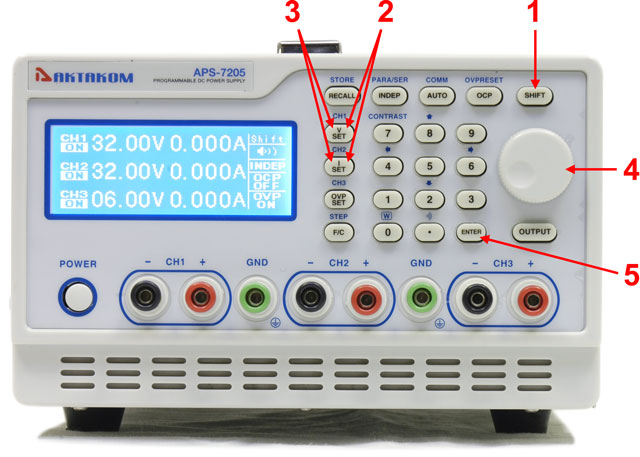
How to set the output voltage or current using the rotary encoder? |
To set the output voltage or current on APS-7205 DC power supply do the following:
- Press SHIFT button to select the secondary function mode.
- Press CH1 or CH2 button to select the desired channel.
- Press V SET button to set the output voltage or press I SET button to set the output current.
- Press the encoder, then rotate it to change the value.
- Press ENTER button to confirm setting.
Up
|
Why does my APS-7306L(LS) power supply not work with LAN cable connected? |
If your APS-7306L(LS) programmable power supply is not working through the LAN (Ethernet) connection, there are a few common reasons:
-
USB connection priority: The APS-7306L(LS) power supply gives priority to the USB interface. If the USB cable is connected, the LAN (Web, LXI) interface will not function. To use LAN control, disconnect the USB cable from the power supply.
-
Incorrect IP address settings: If the IP address in the power supply settings is incorrect, the LAN connection will not work. To configure the correct IP:
-
Connect the APS-7306L(LS) via USB.
-
Use software such as Aktakom Power Manager Max.
-
Open the Connection Settings window by pressing the Connect button.
-
Set the correct IP address and click Write LAN Options to Power Supply.
-
If necessary, you can also reset the LAN settings to default values.
This ensures that your APS-7306L(LS) power supply works correctly over LAN without conflicts.
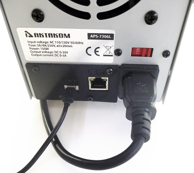
Fig. 1. USB connection
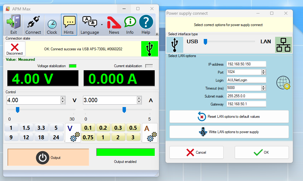
Fig. 2. Main program window and connection settings window
Up
|
I was told there is a video tutorial for this device, where can I see it? |
To watch a video tutorial please go to "Video" section.
Up
|
Can I store voltage and current values in the device memory? |
Yes. The AKTAKOM APS-7306 programmable power supply allows you to store up to 3 sets of voltage and current values in its internal memory for quick recall.
The procedure for saving voltage and current settings is simple:
-
Set the desired voltage and current output (for example, 5V / 1A).
-
Press MEM and then M1 to save this setting.
-
Adjust to the next required values (for example, 12V / 2A).
-
Press MEM and then M2 to save the second set.
-
Finally, set the third output values (for example, 24V / 3.5A).
-
Press MEM and then M3 to store the third configuration.
This feature makes it easy to recall frequently used voltage and current settings without re-entering values manually, improving workflow and efficiency in laboratory or testing environments.
See Video Tutorial for real life application
Up
|
What operating modes does the APS-7306(L/LS) DC Programmable Power Supply have? |
The APS-7306(L/LS) programmable DC power supply supports two main operating modes:
-
Constant Voltage (CV) Mode – Voltage Stabilization
-
This is the most commonly used operating mode.
-
When you press the Output button, the display shows the set voltage, while the current is measured in real time.
-
If the current draw increases and reaches the set maximum limit, the power supply automatically switches to Constant Current mode to protect the load.
-
Constant Current (CC) Mode – Current Stabilization
-
In this mode, the power supply lowers the output voltage so that the current does not exceed the set maximum value.
-
It is important to set the maximum current value before operation.
-
If the maximum current is set to zero, no voltage will appear at the output when you press Output.
-
We recommend setting the current to the minimum required value to protect sensitive electronic devices from accidental short circuits or overloads.
By automatically switching between CV mode and CC mode, the APS-7306(L/LS) ensures stable operation and safe protection for your test circuits and electronic equipment.
Up
|
How do I connect the program software for APS-7306LS DC Programmable Power Supply? |
To connect the APS-7306LS programmable DC power supply to its control software, follow these steps:
-
Connect the USB cable from the APS-7306LS to your computer.
-
Launch the power supply control software (for example, Aktakom Power Manager).
-
The program will automatically detect and connect to the APS-7306LS.
⚠️ Important note: While the APS-7306LS is connected via USB and controlled by software, manual front-panel control will be disabled. To return to manual operation, disconnect the USB connection and restart the power supply by turning it off and back on.
This ensures smooth switching between software control and manual control of the APS-7306LS.
Up
|
What software should I download to work with the APS-7306LS DC Programmable Power Supply? |
Up
|
How to memorize the voltage and current values? |
The APS-7306(L/LS) programmable DC power supply allows you to store up to 3 sets of voltage and current values in its memory for quick recall. This feature is useful for laboratory work, testing, or when frequently using the same output settings.
To memorize voltage and current values:
-
Set the desired output (for example, 5V / 1A).
-
Press MEM and then M1 to store this setting.
-
Adjust to another set of values (for example, 12V / 2A).
-
Press MEM and then M2 to store the second setting.
-
Set a third output value (for example, 24V / 3.5A).
-
Press MEM and then M3 to save the third configuration.
Once stored, you can recall these saved values instantly, without re-entering them each time. This makes the APS-7306(L/LS) more efficient and reliable for repeated power supply tasks.
Up
|
How to configure the program's interface window? |
The control software for the APS-7306LS programmable DC power supply is designed with several functional blocks that make it easy to monitor and adjust voltage and current settings:
-
Top Block – Program Setup & Information
-
Options to customize the program window (hide clock, remove signatures, disable ads).
-
Access to HELP for user assistance.
-
Initialization Box
-
Displays the connected device (e.g., APS-7306LS).
-
Measurement Box (Main Window)
-
Shows the real-time output voltage and current values.
-
Indicates the current operating mode:
-
CV – Constant Voltage (Voltage Stabilization)
-
CC – Constant Current (Current Stabilization)
-
SetUp Box
-
Provides different ways to enter voltage/current values:
-
Manual numeric input
-
Up / Down buttons
-
Slider (left/right)
-
Quick access to pre-specified values
-
To configure preset values, press the gear button to open the preset list.
-
You can edit existing values, add new presets, or delete values from the list.
-
Bottom of the Window – Output Control
-
A large Exit button allows you to connect the load to the power supply output.
This structured software interface makes it simple to configure, store, and recall settings while ensuring precise control of the APS-7306LS DC power supply.
Up
|
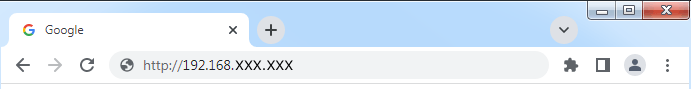
How to check power supply network settings? |
- Connect the power supply to the local network using LAN connector.
- Power on the device.
- Open any Internet browser and enter the IP-address of the power supply in its address bar.
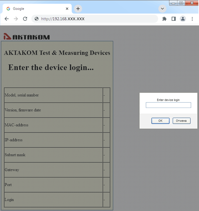
- You should see a window to enter the login assigned to the power supply with AKTAKOM Net Configurator (ANC) program. By default the login window already contains the default login. After entering the login click "OK".
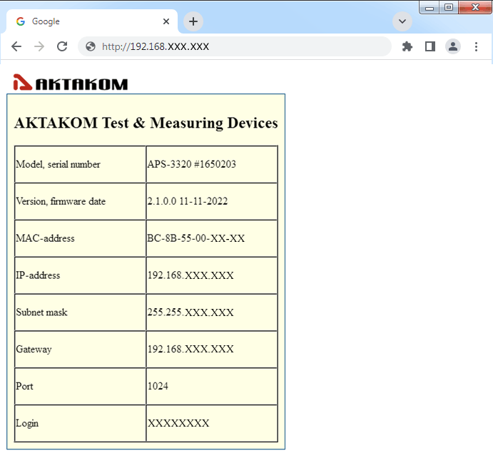
- If the entered login is correct then the browser will display information about the power supply including network settings.
Up
|
How to connect to the sync input of AKTAKOM APS-3xxxLS and APS-7xxxLS power supplies with remote control? |
Sync input is a 2.5 mm audio jack stereo. The counterpart is a 2.5 mm audio jack plug. The scheme of this plug for synchronization signaling, see pic. 1.
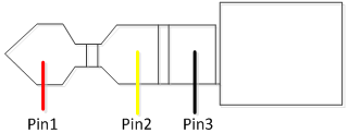
Pic. 1
Pin1: Sync input
Pin2: Reserved
Pin3: Common wire
Parameters of the synchronization control pulse are shown in pic. 2.
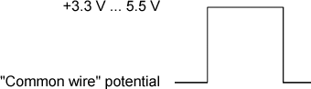
Pic. 2
Note! In APS-7306LS power supply the signal of pin 2 input of the sync connector is also used to reset network settings to default. APS-3xxxLS power supplies do not use this signal.
Up
|
Does the current parameters on AKTAKOM APS-7306 power supply display coincide with the readings of the program? |
Current parameters on AKTAKOM APS-7306 power supply display may not coincide with the program readings if there is no load connected to the device.
Up
|
When I press “Remote” there is nothing happening to AKTAKOM APS-7306 power supply control. What is the reason? |
For safety reasons, the AKTAKOM APS-7306 programmable DC power supply does not allow the remote control mode to be disabled directly from the software. This prevents accidental switching that could endanger the connected electronic equipment.
To return to local (manual) control mode:
-
Turn off the APS-7306 power supply.
-
Turn it back on without connecting it to the computer via USB.
This ensures the safe operation of the power supply and connected devices by requiring a controlled restart before manual control can be restored.
Up
|
What current protection do AKTAKOM power supplies use? |
AKTAKOM programmable power supplies are equipped with different types of protection to ensure safe operation of the device and connected equipment. The protection method depends on the model series:
1. Current Stabilization (CC Mode) – Used in Entry-Level Power Supplies
2. Over Current Protection (OCP Mode) – Available in High-End Power Supplies
-
Advanced AKTAKOM power supplies include Over Current Protection (OCP) in addition to current stabilization.
-
OCP mode is independent of CC mode and allows you to set a specific current limit at which the power supply output will shut off completely.
-
After OCP is triggered, the output terminals remain off until reset manually from the device control panel, regardless of load changes.
-
This provides an additional safety layer, especially for sensitive electronic circuits.
3. Multi-Channel Power Supplies
-
Multi-channel AKTAKOM models support OCP per channel as well as total output current OCP for the entire device.
Key Notes:
-
Devices without OCP rely only on current stabilization (CC mode) for protection.
-
Devices with OCP provide a trigger-based protection that fully shuts off the output.
-
In both cases, when protection is activated, the load is not galvanically isolated from the power supply output terminals.
Up
|
How to set parallel tracking mode when operating Aktakom ATH-22xx? |
- Press both Tracking mode selection keys to enable parallel tracking mode. In parallel tracking mode CH2 output voltage and current value follows CH1 setting. The output current is double to the CH1 display value.
- Use CH1 Voltage knob to adjust the desired voltage output value
- CH1 Current knob to adjust the desired current output value.
- Connect the circuit to the CH1 terminals to get double current output
Below is the illustration of parallel tracking mode
Up
|
How to set series tracking mode when operating Aktakom ATH-22xx power supply? |
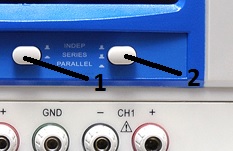
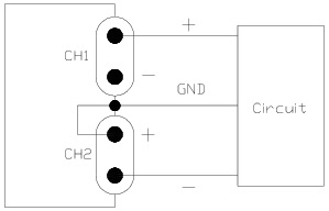
- Press Tracking mode selection key (marked as 1 in the below picture) and release Tracking mode selection key (marked as 2) to enable series tracking mode. In series tracking mode CH2 output voltage and current value follows CH1 setting. The output voltage is double to CH1 display value.
- Turn CH2 Current knob clockwise to maximum current output and then use CH1 Current knob to adjust the desired current output value.
- Use CH1 Voltage knob to adjust the desired voltage output value.
- Connect the circuit to CH1 “+” terminal and CH2 “-” terminal to get double voltage output
- For the bi-polar DC power supply with common ground connect CH2 “+” terminal to “GND” grounding terminal. CH1 “+” terminal is the positive output and CH2 “-” terminal is the negative output
Below is the illustration of series tracking mode
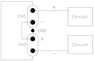
Here is the illustration of Bi-polar tracking mode
Up
|
What is the maximum current consumption of APS-3610 power supply at full load? |
|
At full load 60 V and 10 A (600 W DC) AKTAKOM APS-3610 DC power supply consumes 110 V and 10.4 A, ie 1144 VA.
Up
|
What instruction should I follow to work in the voltage stabilization mode? |
- If OUTPUT indicator is red than press LOAD button. In that case OUTPUT indicator should go out and the current indicator will display the set current value.
- Adjust VOLTAGE adjustment rotary switches in order to obtain the maximum allowable load voltage on the power supply output. If in the operating mode the load resistance change will cause the excess of the specified voltage limit, the power supply will automatically switch to the voltage stabilization mode with setting on terminals «+» and «-» of the preset voltage value limit, and the output current will proportionally fall.
- By using CURRENT rotary switch set the maximum allowable current value (current limit value) for your load.
- Connect the load to the power supply and press LOAD button. OUTPUT indicator should become red.
- Before you disconnect the load press LOAD button. OUTPUT indicator will go out.
- Before switching off the power supply, disconnect the load.
Up
|
How to work in the current stabilization mode? |
- If OUTPUT indicator is red than press LOAD button. In that case OUTPUT indicator should go out and the current indicator will display the set current value.
- By using VOLTAGE adjustment rotary switch set the required output voltage (at the same time nothing should be connected to the output terminals «+» and «-»).
- By using CURRENT rotary switch set the maximum allowable current value (current limit value) for your load. If in the operating mode the load resistance change will cause the excess of the specified current limit, the power supply will automatically switch to the current stabilization mode and the output voltage will proportionally fall.
- Connect the load to the power supply and press LOAD button. OUTPUT indicator should become red.
- Before you disconnect the load press LOAD button. OUTPUT indicator will go out.
- Before switching off the power supply, disconnect the load.
Up
|
How to connect Aktakom APS-3320L power supply to my PC? |
Connection to the PC is made via USB or LAN located on the rear panel of APS-3320L. The first connection to your PC should be made via USB interface. This will help to install the network parameters of your local network for the connection to the power supply. Installation instruction for the network parameters is given in HELP file.
1. For the device automatic search and connection it is not recommended to run AKTAKOM Power Manager Software after the PC installation but at first to connect the USB cable of APS-3320L to the PC and then to run the program agreeing with the device automatic search. You may connect your AKTAKOM power supply to the PC manually, see HELP file.
2. Please note! When you run AKTAKOM Power Manager Software for the first time it will require an access key. This key can be received (copied) at www.tmatlantic.com after APS-3320L registration. The key can be entered later, see Settings/Pass key menu. If you do not enter the key after you run the software this program will operate in demo-mode.
3. State (status) of the AKTAKOM power supply remote control is indicated on the front panel with the connection indicator:
- in the manual control mode – the indicator is OFF,
- USB cable is connected (operation via USB) – the indicator is red,
- LAN cable is connected (USB cable is disconnected) – the indicator is green,
- there is “connected” mode set in the program (the device is operating in the remote control mode, the manual control is OFF) – the indicator is blinking in green or red color.
4. After interface connection, the network cable connection and active work of the local network the indicators of LAN socket should be blinking. Note: when you operate via LAN you need to DISCONNECT the USB cable.
5. USB interface takes priority. After you connect the USB cable the power supply can be controlled via the PC and the program connected via USB.
6. Please note! Be careful! Disconnection of the USB or LAN cable or the controlling program will return the voltage and current values which were set manually using «LOAD» button and the rotary switches on the front panel. Always before entering the remote control mode it’s recommended to switch off «LOAD» button.
If you have any questions concerning the use of interfaces or the software check the detailed description and the section with frequently asked questions at www.tmatlantic.com and www.aktakom.com.
Up
|
How to connect to the power supply via web-interface? |
|
There is no web-interface remote control feature for this power supply. To control the power supply remotely use the software provided in the standard accessory kit for the device.
Up
|
Do AKTAKOM power supplies have short circuit protection? |
|
Yes they have.
Almost all modern power supplies have two operation modes: voltage stabilization mode and current stabilization mode. In case of short circuit the power supply automatically switches from the output voltage stabilization mode to the output current stabilization mode, and the output voltage starts proportionally dropping. At the same time the current in the load connected to the power supply will be limited with the value set with the screwdriver slot used to adjust the output current value on the front panel of the power supply. For the best protection it is recommended to set a low current value. In case of short circuit the current in the connected load will be limited with the value set on the power supply.
Up
|
May I use AKTAKOM power supplies to charge accumulators? |
AKTAKOM power supplies can’t be used for accumulator charging since it may cause the accumulator breakage (recharge, electrolyte boiling, extra pressure of the internal gas which will lead to the accumulator explosion). Accumulators should be charged with the current source which controls the accumulator voltage and regulates the charging current accordingly. When the required accumulator voltage is achieved such type of source simply stops the charging process, its name is a charging device.
Up
|
Can I ground one of “+” or “-” terminals when using AKTAKOM APS-1915 power supply? |
|
It’s not recommended to connect “+” or “-” to “ground” terminal!
Up
|
How to set the timer delay parameters when using Rigol DP832A power supply? |
Press “Timer’ → “Delay Set” to enter the delay parameter setting interface as shown in the figure below. The channel currently selected is displayed in the status bar. Press the channel selection keys at the front panel to switch the channel currently selected. This interface provides delay parameter preview. User can view the values on the current page of the delay parameter list (high level indicates turning on the output and low level indicates turning off the output).
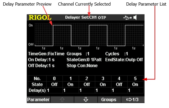
You can set the delay parameters in the delay parameter setting interface following the steps below.
- To Set the Number of Output Groups
- To Set the Number of Cycles
- To Set the End State
- To Edit the Delay Parameters
- To Set the Stop Condition
- To Save and Read the Delay File
Up
|
How to set the timer delay parameters when using Rigol DP832 power supply? |
Press “Timer’ → “Delay Set” to enter the delay parameter setting interface as shown in the figure below. The channel currently selected is displayed in the status bar. Press the channel selection keys at the front panel to switch the channel currently selected. This interface provides delay parameter preview. User can view the values on the current page of the delay parameter list (high level indicates turning on the output and low level indicates turning off the output).
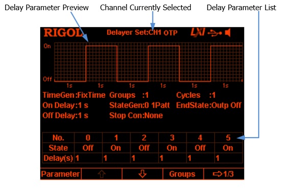
You can set the delay parameters in the delay parameter setting interface following the steps below.
- To Set the Number of Output Groups
- To Set the Number of Cycles
- To Set the End State
- To Edit the Delay Parameters
- To Set the Stop Condition
- To Save and Read the Delay File
Up
|
How to set the timer parameters when operating Rigol DP832A power supply? |
Press “Timer” → “Timer Set” to enter the timer parameter setting interface as shown in the figure below. The channel currently selected is displayed in the status bar.
You can press the channel selection keys at the front panel to switch the channel currently selected. This interface provides timer parameter preview; user can view the values on the current page of the timer parameter list (the horizontal axis denotes time and the vertical axis denotes voltage and current).
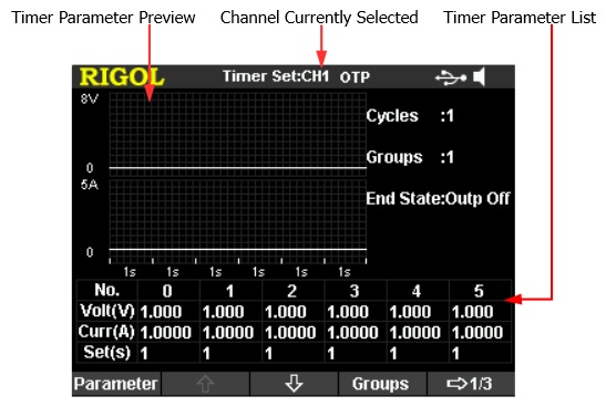
You can set the timer parameters in the timer parameter setting interface following the steps below:
- To Set the Number of Output Groups
- To Set the Number of Cycles
- To Set the End State
- To Edit the Timer Parameters
- To Save and Read the Timer File
Up
|
How to set the timer parameters when operating Rigol DP832 power supply? |
Press “Timer” → “Timer Set” to enter the timer parameter setting interface as shown in the figure below. The channel currently selected is displayed in the status bar.
You can press the channel selection keys at the front panel to switch the channel currently selected. This interface provides timer parameter preview; user can view the values on the current page of the timer parameter list (the horizontal axis denotes time and the vertical axis denotes voltage and current).
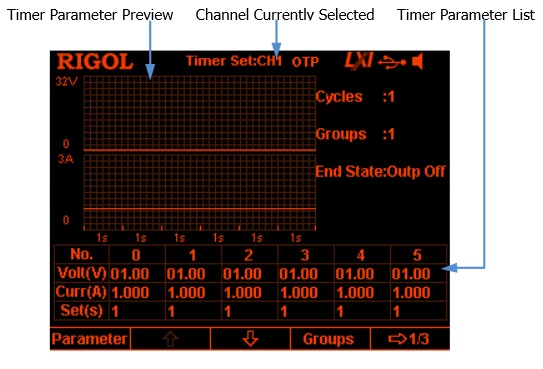
You can set the timer parameters in the timer parameter setting interface following the steps below:
- To Set the Number of Output Groups
- To Set the Number of Cycles
- To Set the End State
- To Edit the Timer Parameters
- To Save and Read the Timer File
Up
|
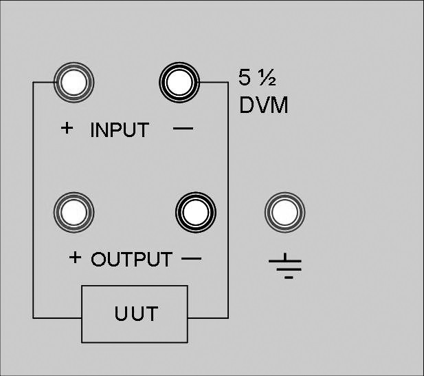
How to work in Voltmeter mode of APS-7151 power supply? |
The voltage of the instrument under test can be measured if the wires are connected together just like it’s shown in the picture below. The power supply can be worked as a voltmeter as long as it is not measuring the resistance. The accuracy of the voltmeter is 5 ½.
Up
|
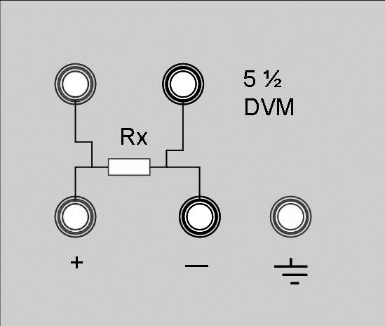
How to work in Milliohmmeter mode of APS-7151 power supply? |
The power supply provides the four-line electrical resistance measurement, just as showed in the diagram below, which can measure accurately the low resistance and the maximum measurement resistance is 10Ω. In order to avoid the damage of the resistance under test, please make sure the resistance under test is within the measurement range.
Three measurement ranges can be optional: 0.1Ω, 1Ω, 10Ω.
Operation Method:
1) Press the keys Shift and V/mΩ (VFD display screen shows----,----mΩ, Range:0.1Ω) to measure the resistance.
2) Press the keys Shift and 0.1Ω or 1Ω or 10Ω to set different measurement range of Milliohmmeter.
Up
|
How to activate remote measurement function of APS-7151 power supply? |
When the load consumes high current, the power supply will produce voltage drop in the connecting wire between power supply and load terminals. In order to guarantee the measurement accuracy, remote measurement terminals is installed at the rear-panel of the power supply. Users can measure the output terminals voltage of the instrument under test by these terminals.
Before performing the remote measurement function, you need to set the power supply as the remote measurement mode.
Please refer to the below diagram for the trigger terminals and measurement terminals.
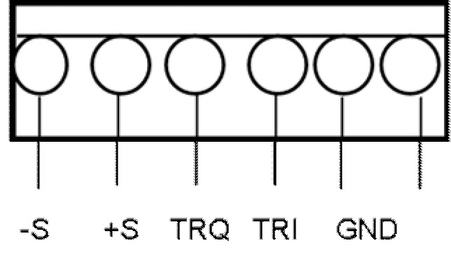
-S and +S are remote measurement terminals; TRQ and TRI are trigger terminals, GND is ground terminal.
The TRQ is trigger output port under auto test mode. The TRQ is default as low voltage level. The TRQ provides +5V for external use when the trigger event happens.
As a multifunction extended port, TRI port is designed for trigger test in the list mode and auto test mode, TRI is also used to switch the ON/OFF state and used as TRI KeepOut port. The TRI is default as high voltage level of +5V. The TRI completes trigger when it change to low voltage level.
Up
|
Making OCP on and pressing output switch; and then the output is automatically shut off. |
|
Current protection value setup is too small. You could press output switch and then make OCP on.
Up
|
Output voltage rises slowly when output button is on. Why? |
|
Current setup is too small.
Up
|
Pressing ON/OFF, there is no output when power on. Why? |
|
Current setup is 0.
Up
|
The panel buttons don't work when power on. Why? |
|
The panel is locked. Press the key [LOCK/UNLOCK] for over 2 seconds, and then the panel will unlock.
Up
|
How to find MAC address of a power supply with LAN interface? |
As for any other network device MAC address (Media Access Control, a device physical address in the network) can be determined by standard means of the operating system such as getmac, nbtstat, ping and arp.
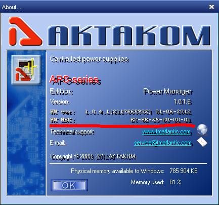
But for a device connected via network to APM program there is a method much simpler. Open “About the program…” (in Help menu) and read the device MAC address in «HW MAC» line.
Up
|
How to connect APS-7303L (APS-7305L) power supply to the program? |
There can be two ways of connection: via USB interface or via LAN interface (TCP/IP protocol).
1) Connection via USB
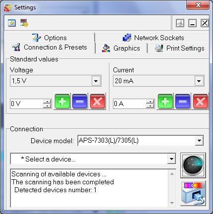
Open Settings window (in Settings main window – Settings panel or just Ctrl+O keys). Go to Connection and Presets tab. Select the right device type you need in the list of models and click “Detect”: .jpg)
After the scanning select the device you need in the list of detected devices and click “Connect”: .jpg)
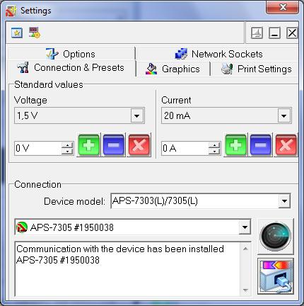
Now the device is connected to the program and ready for further operation.
2) TCP/IP connection
Network connection requires one prior stage: the device socket should be added.
In Settings window go to Network Sockets, enter the device IP-address into Name column in accordance with its network settings. Check Port and Login columns, they should correspond with the device settings as well. Click “Add”: 
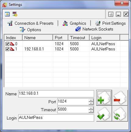
A line with the device network settings will be added to the network sockets list.
Afterwards do the steps similar to the connection via USB.
Up
|
How to see a device serial number in AKTAKOM Power Manager software? |
The program automatically reads the serial numbers of all devices found. To detect the device open Settings window, go to Connection and Presets tab, select the right device type you need in the list of models and click “Detect”:
In the list of detected devices you will see all names and serial numbers of the devices found.
After you select one of the detected devices and connect it to the program its serial number will be displayed in the program main window title.
Up
|
How to install the device driver for the operation via USB? |
Device USB driver can be installed in several stages.
At the first stage files necessary for the driver installation should be copied to the PC hard disk. It happens during APM program installation. At this moment the device shouldn’t be connected to the PC USB port.
When the installation is completed the installer will suggest connecting the device via USB, afterwards it will start installing the copied driver files into the operating system.
If you missed this stage or for some reason driver auto installation failed you may install the driver manually in an ordinary way for Windows any time in the future. In this case connect the device to your PC, wait for Add New Hardware Wizard and specify the path to the driver files on the installation disk or in the working folder of the installed program, for example: «C:\Program Files (x86)\AKTAKOM\AKTAKOM Power Manager\Driver».
Up
|
Can APS-3205 (APS-3203) power supply be used to supply the amplifiers on operational amplifiers? |
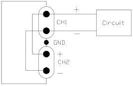
These amplifiers require bipolar power supply +15 V.
In APS-3205 (APS-3203) such bipolar power supply is provided by the connection of output sockets of two different channels in order to get a general output (pic.1). Such a connection is very similar to the connection of two batteries to get a general power output (pic.2).
It’s recommended to choose tracking – control mode in the power unit. In that case supply voltage change will be made simultaneously in two channels of the power supply and voltage in two amplifier arms will be the same respectively.
Up
|
How to change voltage and current values? |
To change voltage and current values use "V SET", "I SET" buttons and adjusting knob as shown below:
Up
|
|
|
