|
Frequently Asked Questions
D.E.V.I.C.E. (Wiki)
Can a transformerless power supply be used for circuits requiring more than 200 mA?
Why does the output voltage of a transformerless supply drop when the load current increases?
What is the difference between an average-responding multimeter and a True RMS multimeter?
How do you calculate the RMS voltage of a non-sinusoidal triangle wave?
What does RMS voltage physically represent in alternating current engineering?
What is the conversion factor for a square wave RMS calculation?
How do you convert peak voltage to RMS voltage for a sine wave?
How do engineers stabilize a practical, real-world op amp differentiator circuit?
Why are ideal op amp differentiators prone to severe high-frequency noise amplification?
What happens if a steady DC voltage is applied to an op amp differentiator?
What are the main limitations and safety risks of transformerless power supplies?
What is the mandatory purpose of the bleeder resistor in a capacitive drop layout?
How does a capacitive transformerless power supply drop AC mains voltage safely?
What type of capacitor is required for a transformerless AC to DC drop circuit?
How do you calculate the current output of a capacitive transformerless power supply?
What is the difference between a standard solenoid and a toroid inductor calculation?
How does adding a ferrite core alter the solenoid inductance calculation matrix?
Why is there a variance between US liquid gallons and Imperial gallons during volume conversions?
How do SMD resistor case sizes (like 0805 or 0603) relate to their power dissipation ratings?
What is the difference between thick film and thin film SMD resistors?
Can I use this calculator to determine the reactance of a transformer winding?
How do you calculate the total inductive reactance of multiple inductors wired in series?
Why is inductive reactance referred to as an "imaginary" or reactive quantity in complex numbers?
What is the difference between Self-Resonant Frequency (SRF) and inductive reactance?
How does a saturation core affect an inductor's reactance?
Can you substitute a color-coded axial inductor with a standard resistor of the same physical shape?
Why do some axial inductors have a wide or double-width second band?
How does wire resistance affect high-frequency AC signals?
What is the difference between solid and stranded wire resistance?
Why does wire resistance increase as the temperature goes up?
Can I use this calculator to design a reliable backup fuse for a circuit?
Does wire insulation affect the calculated fusing current?
What is wire fusing current?
What are the standard circuit breaker amperage sizes in the US?
Can a 20A breaker handle a continuous 20A electrical load?
What happens if my calculated breaker size falls between standard manufacturing limits?
What is the 125% rule for sizing circuit breakers according to the NEC?
How do you convert torque from Newton-meters (Nm) to Foot-pounds (ft-lbs)?
How do you convert pressure from Bars to Pounds per Square Inch (PSI)?
How do you convert mechanical power from kilowatts (kW) to horsepower (hp)?
How do you convert area from square meters to square feet?
How do you convert liquid volume from liters to gallons?
How do you convert temperature between Celsius (°C) and Fahrenheit (°F)?
How do you convert weight from kilograms (kg) to pounds (lbs)?
How do you convert speed from kilometers per hour (km/h) to miles per hour (mph)?
How do you convert length from meters to feet and inches?
What is the difference between an op amp differentiator and an op amp integrator?
How does the integration time constant (RC) affect the output signal's slope?
Why do real-world op amp integrators require a large resistor in parallel with the feedback capacitor?
What happens if a constant DC voltage is applied to an ideal op amp integrator?
Can I use a summing amplifier circuit to mix alternating current (AC) audio signals?
How do power supply rails affect the output calculation boundaries?
What is the concept of a "virtual ground" in a summing amplifier circuit?
What is the difference between Lithium-Ion and Lithium-Polymer power banks?
How does fast charging (9 V or 12 V) affect power bank efficiency calculations?
What is the maximum power bank capacity allowed on commercial flights in the US?
Why can't a 10,000 mAh power bank charge a 4,000 mAh phone exactly 2.5 times?
How do I calculate the required inductance if my target frequency and capacitance are fixed?
Why does a real-world LC circuit eventually stop oscillating?
How do you choose component values if multiple L and C combinations yield the same frequency?
What happens to electrical energy inside an LC tank circuit at resonance?
What is the difference between inductive reactance and resistance?
Why does inductive reactance increase as frequency climbs?
Can this calculator process a combination of both simultaneous voltage and current regulation?
What are the input voltage rules for both modes on this calculator?
When should I use the calculator in Voltage Regulator Mode vs Current Limiter Mode?
Can I substitute an LM317 with an LM350 or LM338 using the same resistor values?
Why is my LM317 or LM338 regulator getting extremely hot during operation?
How do I calculate the resistor for an LM317 constant current LED driver?
How do you calculate the resistor values for a specific LM317 output voltage?
What is the ideal value for resistor R1 in an LM317 voltage regulator circuit?
Does the order of resistors matter in a series circuit?
What happens if one resistor fails or opens up in a series network?
Why would an engineer connect resistors in series instead of using a single resistor?
What happens to current and voltage in a series resistor string?
Can I use this calculator to find equivalent impedance for AC signals?
How do you calculate parallel resistors with identical values?
Why is the total resistance in a parallel circuit less than any single resistor?
Can this calculator process negative dB values for system attenuation?
What is the difference between dB, dBm, and dBV?
Why do engineers add decibels together instead of multiplying them?
What does a -3 dB change mean for power vs. voltage?
What is the difference between 10 lg and 20 lg in dB calculations?
Can I safely measure a blank SMD inductor directly on the PCB?
Why does a code like "100" on an SMD inductor mean 10 µH instead of 100 µH?
Can a voltage divider calculate alternating current (AC) signals?
How do I choose between high resistance (Megohms) and low resistance (Ohms) for R1 and R2?
Why shouldn't a voltage divider be used as a power supply for heavy loads?
How do you choose the right resistor values for a 5V to 3.3V voltage divider?
Does Ohm's Law apply to AC (Alternating Current) circuits?
Why does current drop when resistance increases if voltage stays constant?
How do I choose the correct wattage rating for a resistor using this calculator?
Does a passive low-pass filter affect the input impedance of a circuit?
Why is a low-pass filter necessary before an Analog-to-Digital Converter (ADC)?
What is the difference between a first-order and a second-order low-pass filter?
How do you use an RC low-pass filter to smooth a PWM signal into DC voltage?
What is the difference between a passive high-pass filter and an active high-pass filter?
How do I choose the resistor and capacitor values for an audio high-pass filter?
Why is the cutoff frequency of a filter called the -3dB point?
What happens to the signal below the cutoff frequency in a high-pass filter?
What is the difference between capacitive reactance and impedance?
How do you identify the polarity of SMD tantalum vs electrolytic capacitors?
Why are most ceramic SMD capacitors (MLCC) completely blank with no markings?
How do I read a 3 digit SMD capacitor code?
Can I use standard resistor color codes to build the calculated circuit?
How do the input voltage limits affect the calculation boundaries?
Why does a mismatch in the R4 / R3 resistor ratio cause measurement errors?
How do you calculate the resistor R1 for a targeted output voltage?
Why is duty cycle critical for power dissipation and thermal management?
What is the difference between duty cycle and frequency?
How do I calculate the duty cycle of a 555 timer circuit?
What happens if a PWM signal has a 100% duty cycle?
What is the formula to calculate duty cycle from frequency?
What does a gold or silver multiplier mean in an inductor color code?
How do you read a 4 band inductor color code?
What is the base unit of measurement for the inductor color code?
Why does my resistor color code calculator result not match standard resistor values?
Which way do you read resistor color codes when both ends look identical?
What is the 10kΩ resistor color code for 4-band and 5-band components?
How do I read a 4-band resistor color code?
Can I calculate the resistor value if I already have a specific capacitor?
How do I trigger the output in Monostable mode?
What is the difference between Monostable and Astable mode?
Why students and professionals need IC 555 in monostable mode calculator?
Why do I need to worry about the resistor's wattage?
Can I use one resistor for multiple LEDs in parallel?
What if the calculated resistance isn't a standard resistor value?
How do I find the "Forward Voltage" and "Forward Current" of my LED?
What happens if I don't use a resistor with an LED?
Why students and professionals need series LED resistor calculator?
Why is impedance matching important in transformers?
What happens to the current in a step-up transformer?
What is the "Turn Ratio" of a transformer?
Why students and professionals need ideal transformer calculator?
What are "Web-Safe" colors?
What is the difference between HEX and RGB color codes?
Why students and professionals need this color picker?
Are color codes still used on modern capacitors?
Why are some bands wider than others?
Does the color code tell me the voltage rating?
How do I read capacitor color bands?
Why students & professionals need the capacitor color code calculator?
How does Power Factor affect my 3-phase calculation?
Can this calculator be used for motors?
What’s the difference between single-phase and three-phase power?
What is a three-phase power system?
Why students & professionals need the 3-phase calculator?
Is this calculator suitable for students?
What units does the calculator use?
Can this calculator be used for real construction projects?
What is the difference between area and volume?
Why students & professionals need the area and volume calculator?
Is capacitive reactance the same as resistance?
Can this calculator be used for 50 Hz and 60 Hz systems?
Why does capacitive reactance decrease as frequency increases?
What is capacitive reactance?
Why students & professionals need the capacitive reactance calculator?
Does this calculator include tolerance or voltage rating?
Why don’t capacitors show values directly?
Can this calculator convert capacitor values to microfarads?
Does this calculator work for ceramic capacitors?
What does a capacitor code like "104" mean?
Why students & professionals need the capacitor code calculator?
Is this calculator suitable for DIY home projects?
Why does my breaker keep tripping even though it’s the right size?
Does this calculator work for 120V and 240V circuits?
Can I replace a breaker with a higher amp rating?
How do I know what size circuit breaker I need?
Why electricians need the circuit breaker size calculator?
Why is my measured gain different from the calculated gain?
Does this calculator account for bandwidth limitations?
Why does resistor ratio matter more than absolute value?
Can this calculator be used for any operational amplifier?
What is the difference between inverting and non-inverting op-amp gain?
Why engineers need the Operational Amplifier Gain Calculator?
Does attenuation affect impedance matching?
Can this calculator be used for RF applications?
When should I use a Bridged-T attenuator?
What is the difference between Pi and T attenuators?
Why engineers need the Pi, T & Bridged-T Attenuator Calculator?
When should I use a current divider instead of a voltage divider?
What is the current divider rule?
How does a current divider calculator work?
What Is the current divider calculator used for?
How to Find and Replace a Burned SMD Resistor in Home Electronics?
How to Identify SMD Resistors When Designing or Testing PCBs?
How to Read SMD Resistor Codes on a Smartphone or Laptop PCB?
How to extend battery life?
Can I use battery life calculator for solar-powered or rechargeable systems?
Does voltage affect battery life?
Can I calculate battery life for variable loads?
Why does my battery drain faster than calculated?
What is the difference between nominal and actual battery capacity?
How accurate are the results?
Can I use this calculator for any battery type?
What factors can affect real battery life?
How to Calculate the Cutoff Frequency of a Low-Pass Filter? Simple Examples
How to calculate capacitive reactance (Xc)? Simple examples of application
How to select safe wire size for a 110 V Household?
How to select inductance for a matching LC network at 2.4 GHz with a chosen small SMD capacitor?
How to select a capacitor for an LC tuner circuit at 100 MHz?
How to calculate the secondary current for a step-up transformer?
How to calculate the secondary voltage for a step-down transformer?
How to calculate breaker size for a refrigerator?
How to adjust variable time for off delay timer?
How should the circuit (Fig 2) be modified if a 12V DC motor is used?
How do I know if plugging several electrical appliances in the outlet will trip the circuit breaker?
Can a transformerless power supply be used for circuits requiring more than 200 mA? |
|
Practically, no. Sourcing 200 mA from a 120 V / 60 Hz line requires an exceptionally large X2 capacitor value (approximately 4.4 µF). A safety capacitor of this value is physically bulky, expensive, and creates significant reactive power distortion on the AC line, defeating the primary advantages of size and cost savings.
Up
|
Why does the output voltage of a transformerless supply drop when the load current increases? |
|
This circuit configuration behaves as a constant current source rather than a constant voltage source. The maximum current is strictly governed by the fixed impedance of the X2 capacitor. If your load attempts to draw more current than the capacitor's reactance allows, the voltage across the load will collapse toward zero because there is no reserve energy storage reservoir, unlike in traditional magnetic transformer systems.
Up
|
What is the difference between an average-responding multimeter and a True RMS multimeter? |
|
A standard, low-cost multimeter measures the average rectified AC voltage and multiplies it by an artificial scaling factor of 1.11 to guess the RMS value. This guess is only accurate for pure sine waves. If you try to measure a distorted square wave or variable speed drive signal with a basic meter, the reading will be up to 40% wrong. A True RMS multimeter uses advanced internal analog computing chips to sample the wave geometry and mathematically solve the Root Mean Square equation in real-time, delivering perfect accuracy on any signal shape.
Up
|
How do you calculate the RMS voltage of a non-sinusoidal triangle wave? |
|
True RMS calculations change depending on the geometric area under the signal curve. For a symmetrical triangle or sawtooth wave, the root mean square calculation scales down by the square root of 3: VRMS = Vp / √3.
Up
|
What does RMS voltage physically represent in alternating current engineering? |
|
RMS stands for Root Mean Square. It represents the equivalent DC voltage required to produce the exact same amount of thermal heat dissipation across an identical resistive load. For example, an AC heating element driven by 120 VRMS generates the identical thermal energy and temperature rise as a steady 120 V Direct Current (DC) battery bank source.
Up
|
What is the conversion factor for a square wave RMS calculation? |
|
For a perfectly symmetrical, zero-offset AC square wave, the peak voltage is exactly equal to the RMS voltage, meaning the multiplier constant is 1.0. Because the voltage plateau stays at the maximum positive or negative limit for the entire duration of the cycle, it delivers the absolute maximum possible energy across a load.
Up
|
How do you convert peak voltage to RMS voltage for a sine wave? |
|
To convert peak voltage (Vp) to Root Mean Square voltage (VRMS) for a pure, undistorted sinusoidal wave, multiply the peak value by the mathematical constant 0.7071 (which is 1 / √2). If you need to go backward from a standard US 120 VRMS wall outlet to find the peak voltage, multiply by 1.4142 (√2), which yields roughly 170 Vpeak.
Up
|
How do engineers stabilize a practical, real-world op amp differentiator circuit? |
|
To stabilize the architecture, engineers transform the ideal circuit into a Practical (Band-Limited) Differentiator by adding a small resistor (Rin) in series with the input capacitor, and a small capacitor (Cf) in parallel with the feedback resistor. At high frequencies, these additional components clamp the circuit's maximum gain to a fixed, safe ratio (Amax ≈ –R/Rin), stopping random noise oscillations while preserving standard differentiator performance at low frequencies.
Up
|
Why are ideal op amp differentiators prone to severe high-frequency noise amplification? |
|
The capacitive reactance of the input capacitor drops linearly as frequency rises (XC = 1 / 2πfC). At high frequencies, the input capacitor behaves as a near-perfect short circuit, causing the circuit's total voltage gain (A = –R/XC) to climb aggressively. High-frequency electromagnetic interference (EMI) and thermal noise are amplified exponentially, which can drown out your primary signal and drive the op-amp into high-frequency oscillation or saturation.
Up
|
What happens if a steady DC voltage is applied to an op amp differentiator? |
|
If you apply a steady, unchanging DC voltage to the input, the output voltage drops to exactly 0 Volts. Because a differentiator only responds to the instantaneous rate of change of a signal (dVin / dt), a flat DC baseline has a rate of change of zero, making the mathematical derivative zero.
Up
|
What are the main limitations and safety risks of transformerless power supplies? |
|
The primary limitation is a complete lack of galvanic isolation. The low-voltage DC ground plane is directly tied to either the live or neutral AC power wire. If a user touches any uninsulated metal part of the device, they risk lethal electrocution. Additionally, these circuits are strictly limited to low-current devices (typically under 100 mA), as scaling up the current requires an impractically large and expensive X2 capacitor.
Up
|
What is the mandatory purpose of the bleeder resistor in a capacitive drop layout? |
|
A high-value resistor (typically 470 kΩ to 1 MΩ) must be soldered in parallel directly across the dropping capacitor. When the electrical device is unplugged from the wall socket, the capacitor can store a hazardous, high-voltage DC charge for days. The bleeder resistor provides a slow, safe discharge path that drains this residual voltage down to zero within seconds, preventing severe electrical shock during maintenance.
Up
|
How does a capacitive transformerless power supply drop AC mains voltage safely? |
|
A capacitive power supply utilizes the capacitive reactance of a series capacitor to act as an AC current-limiting element. Instead of dropping voltage by generating massive thermal heat losses (like a resistive voltage divider), the capacitor drops voltage cleanly across a downstream Zener shunt regulator by introducing a 90° electrical phase shift between voltage and current.
Up
|
What type of capacitor is required for a transformerless AC to DC drop circuit? |
|
You must strictly use a specialized metallized film safety capacitor rated Class X2. These components are specifically engineered to connect directly across raw AC power lines (120 V or 230 V). A standard ceramic or electrolytic capacitor will quickly overheat, experience dielectric breakdown, fail closed, and cause a dangerous catastrophic electrical fire.
Up
|
How do you calculate the current output of a capacitive transformerless power supply? |
|
The maximum output current (Iout) depends primarily on the capacitive reactance (XC) of the AC-line dropping capacitor. To find the available current, divide your standard AC mains voltage (Vin) by the reactance value: Iout ≈ Vin / XC, where XC = 1 / (2πfC).
Up
|
What is the difference between a standard solenoid and a toroid inductor calculation? |
|
A solenoid is a straight, open-ended tube layout where the magnetic field lines must travel outside the cylinder through the air to loop back, creating flux leakage. A toroid is a continuous donut-shaped ring where the magnetic field is completely trapped inside the circular core structure. Consequently, toroid calculations do not require Wheeler's short-coil correction factors, resulting in much higher self-containment and minimal electromagnetic interference (EMI).
Up
|
How does adding a ferrite core alter the solenoid inductance calculation matrix? |
|
Introducing a ferromagnetic core multiplies the baseline air-core inductance by the material's relative permeability (µr), modifying the active equation to L = µ0 × µr × N² × A / l. For commercial high-frequency ferrites, µr can range from 20 to over 5,000, causing a massive surge in inductance within the same physical footprint. However, a ferrite core introduces core losses, non-linearities, and magnetic saturation constraints.
Up
|
Why is there a variance between US liquid gallons and Imperial gallons during volume conversions? |
|
The discrepancy is historical and structural. One US Liquid Gallon is legally defined as exactly 231 cubic inches (3.78541 liters). Conversely, one Imperial Gallon (historically used in the UK and Canada) is defined based on the volume of 10 pounds of water, translating to 277.42 cubic inches (4.54609 liters). This converter provides separate configuration parameters for both standards to ensure fluid dynamics and industrial shipping calculations remain strictly accurate.
Up
|
How do SMD resistor case sizes (like 0805 or 0603) relate to their power dissipation ratings? |
The structural dimensions of an SMD resistor package directly dictate its surface area and its ability to radiate thermal energy into the PCB plane. Case sizes use standard imperial naming codes representing length and width measurements: an 0805 package measures approximately 0.08 × 0.05 inches.
- An 0603 package is typically rated for 0.1 W (1/10 W).
- An 0805 package handles up to 0.125 W (1/8 W).
- A larger 1206 package safely dissipates 0.25 W (1/4 W).
Exceeding these continuous wattage limitations causes localized thermal expansion, shifts the internal resistance value, and can crack the solder joints.
Up
|
What is the difference between thick film and thin film SMD resistors? |
The difference lies in the fabrication methodology and electrical performance stability:
- Thick Film Resistors: Manufactured by screen-printing a conductive paste onto a ceramic substrate. They are cost-effective and have high power handling capabilities, but exhibit lower precision (typically ±1% to ±5%) and higher thermal noise.
- Thin Film Resistors: Created via vacuum sputtering a microscopic uniform layer of resistive metal onto the substrate. They offer extreme precision (down to ±0.01%), excellent thermal stability, and exceptionally low noise profiles, making them mandatory for instrumentation amplifiers, medical hardware, and RF circuits.
Up
|
Can I use this calculator to determine the reactance of a transformer winding? |
|
Yes, but only under no-load or isolated conditions. A transformer winding behaves as a standard inductor when the secondary side is open-circuit. However, as soon as a electrical load is connected to the secondary winding, the mutual magnetic coupling introduces a reflected impedance back into the primary winding, which alters the effective current draw and invalidates a simple single-component reactance formula.
Up
|
How do you calculate the total inductive reactance of multiple inductors wired in series? |
|
If multiple inductors are connected in series and are physically spaced far enough apart to prevent their magnetic fields from coupling, their total inductance adds up linearly (Ltotal = L1 + L2 + L3). Consequently, their inductive reactances also add up linearly: XLtotal = XL1 + XL2 + XL3.
Up
|
Why is inductive reactance referred to as an "imaginary" or reactive quantity in complex numbers? |
In advanced electrical engineering alternating current math, impedance is expressed as a complex number: Z = R + jX L (where j is the imaginary unit √–1). It is labeled "imaginary" or "reactive" because, unlike a physical resistor, a pure inductor does not consume or dissipate energy as thermal heat. It merely borrows electrical energy from the source to build a local magnetic field and then throws it back into the circuit during the next half-cycle.
Up
|
What is the difference between Self-Resonant Frequency (SRF) and inductive reactance? |
Every physical inductor has small parasitic capacitances between its physical wire windings. This creates an unintended parallel LC circuit inside the component. The Self-Resonant Frequency (SRF) is the boundary where the inductor's internal capacitive reactance perfectly balances its inductive reactance. Above the SRF threshold, the capacitor characteristics dominate, and the component stops behaving like an inductor altogether, meaning it can no longer block high frequencies.
Up
|
How does a saturation core affect an inductor's reactance? |
|
Inductive reactance relies entirely on a stable inductance (L) value. If the DC current passing through an inductor exceeds its rated magnetic saturation threshold (Isat), the core material (ferrite or iron) cannot store any additional magnetic flux lines. When saturation occurs, the effective inductance drops catastrophically toward zero, causing the inductive reactance (XL) to collapse instantly, turning the inductor into a simple short-circuit wire.
Up
|
Can you substitute a color-coded axial inductor with a standard resistor of the same physical shape? |
|
Absolutely not. Although axial molded inductors often look identical to standard through-hole carbon film resistors in shape, size, and body color, they are completely different physical components. A resistor introduces purely resistive friction (R) to a circuit to drop voltage, whereas an inductor stores energy within a local magnetic field to oppose changes in alternating current via inductive reactance XL = 2πfL. Replacing an inductor with a resistor will break the AC impedance loop, alter tuning frequencies, and potentially cause circuit failure.
Up
|
Why do some axial inductors have a wide or double-width second band? |
|
In some specialized manufacturer marking layouts, a wide or double-width band in the second position indicates a decimal point for low-inductance components under 10 µH, while simultaneously specifying the first significant digit. However, in standard EIA-standard 5-band military configurations, if the first band is a wide military identifier (e.g., Silver), a wide second band of a specific color (like Gold) is used purely to denote a fractional decimal point position before the remaining digits are calculated.
Up
|
How does wire resistance affect high-frequency AC signals? |
At high frequencies (such as radio transmissions or high-speed data arrays), a phenomenon known as the Skin Effect occurs. Alternating current pushes away from the core and travels strictly along the outer layer or "skin" of the conductor. This artificially restricts the usable cross-sectional area, causing the high-frequency AC resistance to be significantly higher than the standard DC resistance calculated by this tool.
Up
|
What is the difference between solid and stranded wire resistance? |
|
For standard DC and low-frequency AC power lines, a solid wire and a stranded wire of the exact same AWG gauge share identical resistance profiles. However, stranded wire has a slightly larger overall outer diameter to account for the air gaps between individual strands, making it highly flexible and resistant to structural stress fractures.
Up
|
Why does wire resistance increase as the temperature goes up? |
|
In metal conductors, heat causes the atomic lattice to vibrate aggressively. These rapid thermal vibrations create a chaotic path for moving electrons, causing them to collide with atoms more frequently. These constant atomic collisions physically restrict electron velocity, causing a measurable spike in total electrical resistance.
Up
|
Can I use this calculator to design a reliable backup fuse for a circuit? |
|
Yes, but you must apply a generous safety margin. Because manufacturing variances in copper purity and ambient humidity alter heat dissipation, structural engineers never run wire traces close to their fusing limit. A reliable circuit trace should operate at no more than 30% to 50% of its calculated fusing current.
Up
|
Does wire insulation affect the calculated fusing current? |
|
The melting point of the metal core (e.g., 1085 °C for copper) stays the same, but the insulation material dictates safe operating limits. Standard PVC insulation melts at just 105 °C. This calculator computes the metal fusion point, meaning the wire insulation will typically smoke, char, and catch fire long before the metal hits the calculated fusing threshold.
Up
|
What is wire fusing current? |
|
Wire fusing current is the critical electrical threshold where the heat generated by current density exceeds the thermal dissipation capabilities of the wire, forcing the metal conductor to instantly melt and open the circuit. It represents the absolute physical failure point of a bare or insulated wire.
Up
|
What are the standard circuit breaker amperage sizes in the US? |
As defined by there are standard fixed ratings including 15, 20, 25, 30, 35, 40, 45, 50, 60, 70, 80, 90, 100, 110, 125, 150, 175, and 200 Amperes. This calculator cross-references your inputs against this matrix to recommend a real-world component.
Up
|
Can a 20A breaker handle a continuous 20A electrical load? |
|
No. Standard circuit breakers are only rated for 80% continuous thermal load. A standard 20A breaker can only run a maximum continuous load of 16A (20 × 0.80). For commercial applications requiring a continuous 100% rating, you must buy specialized, expensive "100%-rated breakers" which feature heavy-duty thermal ventilation.
Up
|
What happens if my calculated breaker size falls between standard manufacturing limits? |
|
Under NEC Article 240.4(B), you are legally permitted to use the "Next Standard Overcurrent Device Rating" rule. If your calculated circuit requirement dictates a 22.5A safety threshold, you can safely round up to the next standard industrial breaker size, which is 25A, provided the branch circuit conductors match or exceed that rating.
Up
|
What is the 125% rule for sizing circuit breakers according to the NEC? |
|
The National Electrical Code (NEC) requires branch circuit overcurrent protection devices to be rated at no less than 125% of the continuous load plus 100% of the non-continuous load. A continuous load is any electrical demand that runs continuously for 3 hours or more (such as refrigerator, lights, or HVAC systems). This safety buffer prevents the circuit breaker from overheating and tripping due to ambient heat build-up.
Up
|
How do you convert torque from Newton-meters (Nm) to Foot-pounds (ft-lbs)? |
|
To convert mechanical torque ratings from metric Newton-meters to US Customary foot-pounds, multiply the value by 0.737562. This calculation is heavily used by automotive and robotics engineers when translating engine outputs or electric actuator tightening limits.
Up
|
How do you convert pressure from Bars to Pounds per Square Inch (PSI)? |
|
To convert pneumatic or hydraulic pressure from Bars to PSI, multiply the value by 14.5038. If a piece of industrial pneumatic machinery requires an operating pressure of 6 Bars, you must configure your shop's compressor gauge to match approximately 87 PSI.
Up
|
How do you convert mechanical power from kilowatts (kW) to horsepower (hp)? |
|
To convert mechanical power from kilowatts to standard mechanical horsepower, multiply the kW rating by 1.34102. If you are evaluating an electric vehicle or industrial motor rated at 100 kW, this configuration translates to exactly 134.1 hp.
Up
|
How do you convert area from square meters to square feet? |
|
Because area scales dimensionally in two directions (X × Y), you cannot use the standard linear length multiplier. To convert square meters (m²) to square feet (ft²), you must multiply the value by 10.7639. For example, a 100 m² workshop footprint equals approximately 1,076.4 ft².
Up
|
How do you convert liquid volume from liters to gallons? |
|
To convert volume from liters to US liquid gallons, multiply the value by 0.264172. Be aware that a US gallon (3.785 liters) is physically smaller than an Imperial (UK) gallon (4.546 liters). This unit converter uses the standard US liquid gallon profile as its default volumetric baseline to align with US industrial specifications.
Up
|
How do you convert temperature between Celsius (°C) and Fahrenheit (°F)? |
|
Unlike other dimensions, temperature conversion requires an algebraic offset because their zero-points differ. To convert Celsius to Fahrenheit, use the formula °F = (°C × 9/5) + 32. To convert Fahrenheit back to Celsius, subtract 32 first, then scale it: °C = (°F - 32) × 5/9.
Up
|
How do you convert weight from kilograms (kg) to pounds (lbs)? |
|
To convert mass or weight from kilograms to pounds, multiply the metric value by 2.20462. For instance, a 70 kg equipment chassis weighs roughly 154.3 lbs in the US Customary system. To go in reverse from pounds to kilograms, multiply the value by 0.453592.
Up
|
How do you convert speed from kilometers per hour (km/h) to miles per hour (mph)? |
|
To convert speed from km/h to mph, multiply the velocity value by 0.621371. For example, a European highway speed limit of 130 km/h converts to approximately 80.8 mph. If you are working in scientific environments and need to convert meters per second m/s) to mph, use the multiplier constant 2.23694.
Up
|
How do you convert length from meters to feet and inches? |
|
To convert meters to feet, multiply the length value by 3.28084. If you need to convert centimeters to inches, multiply the value by 0.393701 (or divide the inches by 2.54 to go backward). This calculator handles multi-stage length parsing automatically, allowing you to instantly convert precise architectural or mechanical layouts between metric and US dimensions.
Up
|
What is the difference between an op amp differentiator and an op amp integrator? |
|
The two circuits perform inverse mathematical operations by swapping the physical positions of the resistor and capacitor. An integrator uses an input resistor and a feedback capacitor to calculate the cumulative area under the signal curve over time, which smooths out sharp transitions (e.g., turning square waves into triangle waves). A differentiator uses an input capacitor and a feedback resistor to calculate the instantaneous rate of change of the signal, which sharpens edges and detects transitions (e.g., turning square waves into sharp spikes).
Up
|
How does the integration time constant (RC) affect the output signal's slope? |
|
The time constant τ = RC is inversely proportional to the circuit's integration speed. If you choose small values for R and C, the 1/(RC) multiplier becomes large, causing the output voltage ramp to shoot up incredibly fast (steep slope). If you choose massive values for R and C, the integration slows down drastically, resulting in a very gentle, slow-moving output slope.
Up
|
Why do real-world op amp integrators require a large resistor in parallel with the feedback capacitor? |
|
Real-world operational amplifiers suffer from internal imperfections called input bias currents and input offset voltages. Even with 0 V on the input, these tiny errors act as a permanent DC input signal. Over time, the capacitor integrates this error until the op-amp saturates (drifts to the power rail), rendering the circuit useless. Placing a massive resistor in parallel with the capacitor provides a safe DC discharge path that stabilizes the circuit at low frequencies, transforming it into a practical Lossy Integrator.
Up
|
What happens if a constant DC voltage is applied to an ideal op amp integrator? |
|
If you feed a steady DC voltage (Vin) into an ideal integrator, the circuit will calculate a continuous, linear mathematical accumulation, causing the output voltage to form a steady ramp Vout = -Vin × t / RC. In a real physical circuit, this ramp cannot climb forever; it will quickly hit the op-amp's power supply saturation rails (+Vs or -Vs) and flatten out, stopping any further integration.
Up
|
Can I use a summing amplifier circuit to mix alternating current (AC) audio signals? |
|
Yes, this is the exact engineering principle behind multi-channel analog studio audio mixers. When mixing AC audio waves, the summing amplifier calculates the instantaneous vector sum of all overlapping audio frequencies in real-time. Because of the virtual ground node, there is zero crosstalk or signal bleed between individual microphones or instrument lines, delivering an incredibly clean audio mix.
Up
|
How do power supply rails affect the output calculation boundaries? |
|
A real-world operational amplifier cannot generate an output voltage higher or lower than its physical power supply rails (+Vs and -Vs). If your inputs sum up to a calculated value of -15 V, but your op-amp is powered by a ±12 V rail, the output will flatten out (clip) abruptly near -11 V or -12 V, causing heavy signal clipping and distortion.
Up
|
What is the concept of a "virtual ground" in a summing amplifier circuit? |
|
In an ideal op-amp circuit with negative feedback, the differential input voltage is driven to zero. Because the non-inverting terminal (+) is physically connected to the actual 0 V ground, the op-amp forces the inverting terminal (-) to rest at exactly 0 V as well. This node is called a virtual ground. It is a massive advantage because it mathematically isolates the input channels from one another, preventing changes in one channel's input voltage or resistance from leaking back and interfering with neighboring channels.
Up
|
What is the difference between Lithium-Ion and Lithium-Polymer power banks? |
|
The terms refer to the physical packaging and chemical composition of the internal cells, but they use the exact same 3.7 V nominal calculation math. Lithium-Ion (Li-Ion) cells are typically cylindrical (like standard 18650 cells), rigid, have high energy density, and are cheaper to manufacture. Lithium-Polymer (Li-Po) cells use a flexible pouch format, allowing manufacturers to build ultra-thin, sleek power banks that fit seamlessly into pockets, though they are slightly more expensive.
Up
|
How does fast charging (9 V or 12 V) affect power bank efficiency calculations? |
|
Fast charging protocols (like USB-PD or Qualcomm Quick Charge) boost the output voltage to 9 V or 12 V to deliver more power quickly. Pushing voltage higher causes the available mAh at the port to drop even further during the transfer. Additionally, fast charging forces the internal electronics to run hotter. This increased heat dissipation drops the circuit efficiency factor from roughly 90% down to 80% or lower, resulting in slightly fewer total charge cycles compared to standard slow 5 V charging.
Up
|
What is the maximum power bank capacity allowed on commercial flights in the US? |
|
According to the US Federal Aviation Administration (FAA) and TSA regulations, passenger power banks must be carried strictly in carry-on baggage (never checked luggage) and are capped at a maximum energy rating of 100 Watt-hours (Wh) per battery. To find the Wh rating of a standard 3.7V pack, use the formula: Wh = (mAh × 3.7) / 1000. This means the absolute maximum legal capacity you can fly with without special airline approval is 27,027 mAh.
Up
|
Why can't a 10,000 mAh power bank charge a 4,000 mAh phone exactly 2.5 times? |
|
This is due to two unavoidable factors: voltage conversion and circuit inefficiency. The power bank's internal cells store energy at 3.7 V, but must boost it to 5 V to send it through the USB cable. This step-up process immediately reduces the available mAh rating by about 26%. Furthermore, the internal boost converter and the phone's charging circuitry generate heat, wasting roughly 10% to 15% of the energy. In reality, a 10,000 mAh power bank only delivers around 6,500 mAh of usable capacity at the USB port.
Up
|
How do I calculate the required inductance if my target frequency and capacitance are fixed? |
If you know your target resonant frequency (f) and your available capacitor value (C), you can calculate the necessary inductance (L) by squaring both sides of the Thomson equation and isolating L: L = 1 / 4π²f²C.
This configuration is highly useful when winding custom magnetic coils to match a specific fixed-frequency radio standard or communications link.
Up
|
Why does a real-world LC circuit eventually stop oscillating? |
|
In physical reality, perpetual motion does not exist in electronics. Every real-world inductor possesses an internal DC resistance inside its copper wire windings, and every capacitor suffers from a small Equivalent Series Resistance (ESR). These resistive losses convert a tiny fraction of the oscillating electrical energy into pure heat during each cycle. To prevent this dampening effect from killing the signal, an active component (like a transistor feedback loop) must continuously inject energy into the circuit.
Up
|
How do you choose component values if multiple L and C combinations yield the same frequency? |
|
While many different pairings of L and C can hit your target resonant frequency, engineers select specific values based on the desired Quality Factor (Q-factor) and circuit bandwidth. A high L-to-C ratio (L/C) results in a high-Q circuit with a very narrow, sharp filtering bandwidth. Conversely, a low L-to-C ratio widens the bandwidth, which is useful when you need to pass a broader range of sideband data along with your carrier signal.
Up
|
What happens to electrical energy inside an LC tank circuit at resonance? |
At the resonant frequency, the circuit acts as an electrical pendulum, endlessly sloshing energy back and forth between two states. The capacitor stores energy within its expanding and collapsing electric field, which it then discharges into the inductor. The inductor uses that current to build up a magnetic field, which subsequently collapses and recharges the capacitor in the opposite polarity. In an ideal circuit, this lossless oscillation would continue forever.
Up
|
What is the difference between inductive reactance and resistance? |
|
DC resistance (R) is a static opposition caused by electron collisions within a physical material, and it converts electrical energy into pure heat regardless of frequency. Inductive reactance (XL) is a dynamic opposition caused entirely by magnetic field back-pressure, and it scales linearly with frequency. Combining resistance and reactance together via vector math yields the total AC Impedance (Z), calculated as Z = √(R² + XL²).
Up
|
Why does inductive reactance increase as frequency climbs? |
|
According to Faraday's Law of Induction, an inductor generates a Counter-Electromotive Force (Back-EMF) that directly opposes any changes in current flow. At higher AC frequencies, the current changes its direction and magnitude much more rapidly. This rapid fluctuation forces the inductor to generate a stronger, more aggressive opposing Back-EMF per second, which manifests physically as a higher reactive resistance to the signal.
Up
|
Can this calculator process a combination of both simultaneous voltage and current regulation? |
|
No, because a standard single-chip LM317 circuit cannot regulate both parameters at the exact same split-second. It operates either as a pure voltage source or a pure current source. If a load demands more current than the current limiter setting allows, the regulator drops the voltage down to save the circuit. If you require simultaneous independent clamping of both maximum voltage and maximum current, you must cascade two separate IC stages (an LM317 voltage regulator feeding into an LM317 current limiter).
Up
|
What are the input voltage rules for both modes on this calculator? |
Linear regulators suffer from a "dropout voltage" penalty (typically around 2 V to 3 V).
- In voltage regulator mode: Vin ≥ Vout + 3 V.
- In current limiter mode: Vin must be at least 3 V higher than the maximum forward voltage drop across your load plus the internal 1.25 V drop across R1.
Up
|
When should I use the calculator in Voltage Regulator Mode vs Current Limiter Mode? |
|
Use Voltage Regulator Mode when powering digital microcontrollers (like an Arduino or ESP32), sensor modules, or logic boards that require a strict, steady operating rail (e.g., 3.3 V or 5 V). Use Current Limiter Mode when driving high-power LEDs, charging battery packs (like NiMH or Lead-Acid), or running electroplating tanks, where an uncontrolled spike in current would cause catastrophic thermal runaway.
Up
|
Can I substitute an LM317 with an LM350 or LM338 using the same resistor values? |
|
Yes. Because the LM317, LM350, and LM338 are topologically identical and all use an internal 1.25 V reference voltage, they are drop-in replacements for one another regarding calculation math. You can swap an LM317 for an LM338 to upgrade a circuit's current capability from 1.5 A to 5 A without changing your existing R1 and R2 resistor configuration.
Up
|
Why is my LM317 or LM338 regulator getting extremely hot during operation? |
|
Linear regulators act like variable resistors; they drop excess voltage by converting it into pure heat. The power dissipation (Pd) is calculated as: Pd = (Vin - Vout) × Iload. If you drop 12 V down to 5 V (7 V drop) while drawing 2 A using an LM338, the IC will dissipate 14 W of heat. Without a substantial aluminum heatsink, the chip will quickly hit its internal thermal shutdown limit to prevent burnout.
Up
|
How do I calculate the resistor for an LM317 constant current LED driver? |
When using the calculator in current limiter mode, only resistor R 1 is used to program the target output current. The formula is R 1 = 1.25 / I limit. If you need to drive a high-power LED array at a constant current of 700 mA (0.7 A), the required resistance is 1.25 / 0.7 ≈ 1.78 Ω.
Up
|
How do you calculate the resistor values for a specific LM317 output voltage? |
To calculate the required R2 value for a targeted Vout while using a standard 240 Ω resistor for R1, rearrange the standard formula to:
R2 = R1 × (Vout / 1.25 – 1)
For example, if you need a 5 V output rail: R2 = 240 × (5 / 1.25 – 1) = 720 Ω.
You would select the closest standard EIA precision resistor or use a variable potentiometer.
Up
|
What is the ideal value for resistor R1 in an LM317 voltage regulator circuit? |
|
For standard LM317 circuits, the recommended value for R1 is 240 Ω (or 120 Ω for the LM350 / LM338 series). The regulator requires a minimum load current (typically 3.5 mA to 10 mA) to maintain stable voltage regulation. Using a 240 Ω resistor across the 1.25 V reference pin ensures a constant 5.2 mA draw, satisfying the minimum load requirement under all conditions.
Up
|
Does the order of resistors matter in a series circuit? |
|
No. Because addition is commutative, changing the physical arrangement or order of resistors in a pure series chain has absolutely no effect on the total resistance (RTotal) or the total current draw of the circuit.
Up
|
What happens if one resistor fails or opens up in a series network? |
If a single resistor fails and burns open in a series circuit, it completely breaks the electrical path. Because there are no alternative routes for the current to take, the entire loop drops to zero Amps, and the circuit shuts down entirely — similar to how old Christmas tree lights would go dark if one bulb burned out.
Up
|
Why would an engineer connect resistors in series instead of using a single resistor? |
Engineers often use series chains for two reasons: to achieve a non-standard custom resistance value using common EIA stock components, or to distribute high voltages across multiple components. Spreading a large voltage drop across several resistors prevents arcs and keeps individual components from exceeding their maximum voltage limits or power ratings.
Up
|
What happens to current and voltage in a series resistor string? |
|
According to Kirchhoff's Circuit Laws, the current remains identical through every single resistor in a series chain. However, the total source voltage is divided among them. Each resistor drops a portion of the voltage proportional to its resistance value (V = I × R).
Up
|
Can I use this calculator to find equivalent impedance for AC signals? |
|
Yes, as long as the circuit contains purely resistive loads. If your parallel network includes capacitors or inductors, the calculation shifts because frequency-dependent phase angles must be factored in, requiring vector addition rather than standard scalar algebra.
Up
|
How do you calculate parallel resistors with identical values? |
If all resistors running in parallel share the exact same Ohm value, you can bypass the complex reciprocal math. Simply take the resistance of a single component (R) and divide it by the total number of resistors (n) in parallel: R Total = R / n. For example, three 300 Ω resistors in parallel equal exactly 100 Ω.
Up
|
Why is the total resistance in a parallel circuit less than any single resistor? |
|
In a parallel network, adding more resistors opens up additional paths for electrons to travel through. Even if you add a massive resistor, it still provides a new branch for current flow, reducing the total friction of the circuit. Therefore, the equivalent (total) resistance will always be smaller than the smallest individual resistor in that parallel loop.
Up
|
Can this calculator process negative dB values for system attenuation? |
|
Yes. If the input voltage or power is greater than the output voltage or power (which happens inside passive components, attenuator pads, or long-distance transmission cables), the fraction inside the logarithm becomes less than 1. This naturally generates a negative decibel result. A calculation yielding -20 dB of voltage gain means your output signal has been successfully attenuated down to exactly 10% of its initial input value.
Up
|
What is the difference between dB, dBm, and dBV? |
|
dB is a pure, dimensionless ratio used to compare two arbitrary signal levels (like output vs. input). It tells you how much a signal changed, but not its absolute strength. Conversely, dBm and dBV are absolute units locked to a fixed reference point: dBm measures power relative to exactly 1 milliwatt (1 mW), while dBV measures voltage relative to exactly 1 Volt (1 V).
Up
|
Why do engineers add decibels together instead of multiplying them? |
|
The primary advantage of the decibel's logarithmic scale is that it converts complex multiplication into simple addition. If an RF signal passes through an antenna preamplifier with a gain of +15 dB, a coaxial cable with a loss of -3 dB, and a bandpass filter with a loss of -2 dB, you simply add the values: +15 - 3 - 2 = +10 dB. This represents a net tenfold increase in power, making system-level signal path tracking incredibly fast.
Up
|
What does a -3 dB change mean for power vs. voltage? |
|
The -3 dB mark is a universal milestone in electronics. For power calculations, -3 dB means that the output power has dropped to exactly 50% (half) of the input power. For voltage calculations, -3 dB means the output voltage has dropped to 70.7% (1 / √2) of its original level. This threshold is widely used to define the cutoff frequency boundaries in low-pass and high-pass filters.
Up
|
What is the difference between 10 lg and 20 lg in dB calculations? |
The factor of 10 is used strictly for power quantities ( Watts), while the factor of 20 is used for root-power quantities such as voltage ( Volts) or current ( Amps). Because electrical power scales with the square of the voltage (P ∞ V²), the exponent of 2 is moved to the front of the logarithm function according to standard mathematical rules (10 × 2 = 20). Using 10lg for a voltage ratio will yield a major calculation error.
Up
|
Can I safely measure a blank SMD inductor directly on the PCB? |
No. Just like Multi-Layer Ceramic Capacitors (MLCCs), many ultra-small SMD inductors (especially in 0402 or 0603 footprints) are completely blank. Attempting to measure their value using an LCR meter while they are still soldered to the circuit board will yield completely false data, as the meter will read the parallel impedance paths of surrounding resistors, ICs, and decoupling caps. To get a true inductance reading, you must desolder at least one leg (or isolate the entire chip) and measure it out-of-circuit.
Up
|
Why does a code like "100" on an SMD inductor mean 10 µH instead of 100 µH? |
|
This is the single most common mistake made during manual bench assembly. Under the standard 3-digit marking scheme, the final digit is a multiplier exponent (10x), indicating how many zeros to append to the first two digits. For a code of 100, the multiplier is 100, which equals 1. Therefore, 10 × 1 = 10 µH. To represent a 100 µH inductor, the component must be stamped 101 (10 × 101 = 100).
Up
|
Can a voltage divider calculate alternating current (AC) signals? |
Yes. For pure AC voltage signals (like line audio or low-frequency sine waves), a standard resistor divider works identically to DC, attenuating the peak-to-peak amplitude without shifting the phase. However, if your AC signal runs at high frequencies (RF or high-speed data lines), the parasitic capacitance of the resistors and PCB traces will form an unintended low-pass filter. In those high-frequency scenarios, you must use a compensated divider that incorporates small capacitors alongside the resistors.
Up
|
How do I choose between high resistance (Megohms) and low resistance (Ohms) for R1 and R2? |
|
This is a balance between power consumption and noise immunity. If you choose very low resistor values (e.g., 10Ω), the divider will draw a massive quiescent current from the source, draining batteries and generating heat. If you choose ultra-high values (e.g., 10MΩ), the current draw drops to near-zero, but the output node becomes highly susceptible to stray electromagnetic interference (EMI) and electrical noise, which can corrupt ADC sensor readings. For general electronics, values between 1kΩ and 100kΩ offer the best compromise.
Up
|
Why shouldn't a voltage divider be used as a power supply for heavy loads? |
|
A voltage divider is strictly meant for low-current signal conditioning, not for powering components like motors, heaters, or relays. When you connect a heavy load to Vout, that load acts as a third resistor running in parallel with R2. This drastically alters the overall resistance ratio, causing the output voltage to drop heavily (sag). Furthermore, massive amounts of energy are wasted as pure heat through R1, making it highly inefficient compared to a dedicated buck converter or linear regulator.
Up
|
How do you choose the right resistor values for a 5V to 3.3V voltage divider? |
|
To step down a 5 V logic signal to a safe 3.3 V level, you need a resistor ratio where R2 is approximately double the value of R1. A highly common real-world pairing is setting R1 = 1.8kΩ and R2 = 3.3kΩ. Plugging these into the calculator yields: 5 × (3.3 × 10³ / (1.8 × 10³ + 3.3 × 10³)) approx 3.23 V, which sits safely within the high-logic detection threshold of any standard 3.3 V microcontroller GPIO pin.
Up
|
Does Ohm's Law apply to AC (Alternating Current) circuits? |
Yes, but with an important caveat. For purely resistive AC loads, such as incandescent light bulbs, electric blankets, or water heaters, Ohm's Law applies exactly the same way as it does in DC circuits. However, if the AC circuit contains reactive components like capacitors or inductors, standard DC resistance (R) must be replaced with Impedance (Z), changing the formula to V = I × Z. Impedance accounts for frequency-dependent phase shifts that DC calculations ignore.
Up
|
Why does current drop when resistance increases if voltage stays constant? |
|
Resistance is literally the friction or physical opposition to the flow of electrical charges. Think of voltage as water pressure in a pipe and current as the water flow rate. If you constrict the pipe (increase resistance) while keeping the pump pressure (voltage) exactly the same, less water can push through per second. Therefore, as resistance climbs, the current drops proportionally, which perfectly mirrors the inverse relationship defined by I = V / R.
Up
|
How do I choose the correct wattage rating for a resistor using this calculator? |
|
When adding a physical resistor to a circuit, calculating its resistance is only half the battle; you must also calculate the power it will dissipate. If you calculate that a resistor will drop 5 V while carrying 100 mA (0.1 A), using P = V × I reveals a power dissipation of 0.5 W. Using a standard 1/4 W (0.25 W) resistor in this scenario will cause the component to overheat and burn out. You must select a resistor rated for at least 0.5 W (ideally 1 W for a 50% safety buffer).
Up
|
Does a passive low-pass filter affect the input impedance of a circuit? |
Yes. The total impedance of an RC low-pass filter drops as the signal frequency climbs because the capacitor's reactance falls toward zero. At high frequencies, the input source sees an impedance that effectively equals just the value of the resistor (R) shorted to ground. If R is set too low, it can overload the preceding amplifier stage, dragging down signal amplitude and introducing unwanted harmonic distortion.
Up
|
Why is a low-pass filter necessary before an Analog-to-Digital Converter (ADC)? |
In digital signal processing, an input low-pass filter is mandatory to serve as an anti-aliasing filter. According to the Nyquist-Shannon sampling theorem, an ADC cannot accurately sample any signal frequency that exceeds half of its sampling rate (f s/2). Without a low-pass filter to aggressively choke off those ultra-high frequencies before conversion, they will "fold back" into the lower frequency spectrum, generating permanent digital distortion known as aliasing.
Up
|
What is the difference between a first-order and a second-order low-pass filter? |
The primary difference is the aggressiveness of the attenuation slope in the stopband. A first-order filter uses one resistor and one capacitor, yielding an attenuation slope of 20dB per decade (6dB per octave). A second-order filter cascades two RC stages together (or utilizes an active op-amp topology), doubling the roll-off sharpness to 40dB per decade (12dB per octave) to isolate target signals more effectively.
Up
|
How do you use an RC low-pass filter to smooth a PWM signal into DC voltage? |
A PWM (Pulse-Width Modulation) signal transitions rapidly between high and low digital states. An RC low-pass filter acts as an integrator; by choosing a cutoff frequency (f c) significantly lower than the PWM switching frequency, the capacitor blocks the fast AC switching edges and charges up to the average value of the duty cycle. This converts the digital pulses into a clean, stable analog DC voltage rail.
Up
|
What is the difference between a passive high-pass filter and an active high-pass filter? |
A passive high-pass filter relies entirely on unpowered components (resistors, capacitors, or inductors). While simple and cost-effective, passive filters always introduce a slight insertion loss and cannot amplify a signal. An active high-pass filter combines these passive elements with an operational amplifier (op-amp). This configuration provides isolation, prevents impedance loading bugs, allows for adjustable gain, and makes it easy to construct complex high-order filter slopes without losing signal strength.
Up
|
How do I choose the resistor and capacitor values for an audio high-pass filter? |
|
When selecting component values, you must balance the input impedance of the next stage in your audio chain. If your resistor value (R) is set too low, it will excessively load down the audio source, causing distortion. A standard practice in line-level audio design is to keep the resistor value between 10kΩ and 100kΩ, and then use this calculator to solve for the exact matching capacitance (C) needed to clear out low-frequency mud or DC offsets.
Up
|
Why is the cutoff frequency of a filter called the -3dB point? |
|
The -3dB designation represents the half-power point of the circuit. At this specific frequency, the output power drops to exactly 50% of the input power, and the output voltage drops to 1/√2 (approximately 70.7%) of the input voltage. It serves as the universal engineering standard to mark the boundary line between a filter's passband (allowed frequencies) and stopband (blocked frequencies).
Up
|
What happens to the signal below the cutoff frequency in a high-pass filter? |
|
Below the cutoff frequency, the filter enters its "stopband" region, where it continuously attenuates incoming signals. For a standard first-order passive RC filter, the signal drops at a fixed slope of 20dB per decade (or 6dB per octave). If you require a much steeper drop to aggressively eliminate low-frequency interference, you must cascade multiple stages together to build a second-order (12dB/oct) or fourth-order (24dB/oct) active filter network.
Up
|
What is the difference between capacitive reactance and impedance? |
Capacitive reactance (XC) refers strictly to the opposition to AC current offered by an ideal, pure capacitor. Impedance (Z) is a broader vector sum that represents the total opposition to AC current across an entire circuit network, which may combine standard DC resistance (R), capacitive reactance (XC), and inductive reactance (XL). The relationship is calculated using the formula: Z = √(R² + XC²).
Up
|
How do you identify the polarity of SMD tantalum vs electrolytic capacitors? |
Unlike non-polarized MLCC ceramic chips, tantalum and aluminum electrolytic SMD capacitors are highly polarized and will fail catastrophically if installed backward.
- SMD Tantalum Capacitors: Feature a rectangular body where a solid colored stripe (often dark or white) marks the Positive (Anode) terminal.
- SMD Aluminum Electrolytic Capacitors: Feature a cylindrical metallic tin with a flat base, where a black filled-in wedge or stripe marks the Negative (Cathode) terminal.
Up
|
Why are most ceramic SMD capacitors (MLCC) completely blank with no markings? |
Multi-Layer Ceramic Capacitors (MLCCs) in standard case sizes like 0402, 0603, and 0805 are mass-produced without any surface markings due to physical space constraints and cost optimization. Because the ceramic manufacturing baking process alters the surface profile, printing legible ink or laser codes on millions of tiny components is impractical. To identify a blank SMD capacitor's value, you must desolder the component and measure it out-of-circuit using an LCR meter or a digital multimeter with a capacitance setting.
Up
|
How do I read a 3 digit SMD capacitor code? |
|
To read a standard 3-digit SMD capacitor code, interpret the first two numbers as the base value in picofarads (pF) and the third number as the multiplier (10x). For instance, if the capacitor reads 223, you take 22 and multiply it by 10³ (or add three zeros), which equals 22,000pF. Converting this value yields 22 nF or 0.022 μF. If a lowercase "R" is present, it acts as a decimal point (e.g., 4R7 equals 4.7 pF).
Up
|
Can I use standard resistor color codes to build the calculated circuit? |
|
Yes. When turning the theoretical resistance values (R1, R2, R3, R4) from this calculator into a physical PCB or breadboard prototype, matching the color bands or surface-mount (SMD) codes is critical. For high-accuracy instrumentation circuits, always use 0.1% tolerance metal film resistors to ensure your physical hardware matches the calculator’s output voltage precisely.
Up
|
How do the input voltage limits affect the calculation boundaries? |
|
The calculated Vout is physically limited by the power supply rails of your operational amplifiers. Furthermore, you must ensure that the internal outputs of the first stage do not saturate. If you set the gain via R1 and R2 too high for a given input voltage, the internal nodes will clip, leading to clipped and heavily distorted calculation results at Vout.
Up
|
Why does a mismatch in the R4 / R3 resistor ratio cause measurement errors? |
|
The primary job of the R3 and R4 resistor network is to perform pure voltage subtraction, canceling out any noise that appears equally on both inputs (V1 and V2). If the ratio of R4 / R3 on the top path doesn't perfectly match the R4 / R3 ratio on the bottom path, this common-mode noise will not cancel out. Even a minor 0.1% mismatch can corrupt your output voltage calculations with heavy interference.
Up
|
How do you calculate the resistor R1 for a targeted output voltage? |
If you know your input voltages (V1, V2), your target Vout, and have fixed values for the other resistors (R2, R3, R4), you can calculate the exact required value for R1 by rearranging the formula:
R1 = 2 × R2 / ((Vout / (V2 – V1) × R3 / R4) - 1)
This calculation helps you find the correct resistor value to scale weak millivolt sensor inputs to match the full input voltage range of an Analog-to-Digital Converter (ADC).
Up
|
Why is duty cycle critical for power dissipation and thermal management? |
|
In power electronics, components like MOSFETs dissipate the most heat during the brief transition periods between switching ON and OFF. A higher duty cycle means the component stays in the fully conductive, low-resistance state longer, reducing switching losses relative to conduction time. However, in applications like pulsed lasers or radio transmitters, a low duty cycle is intentionally used to allow components to cool down between intense, high-power bursts, preventing thermal runaway.
Up
|
What is the difference between duty cycle and frequency? |
Frequency determines how many complete wave cycles occur within one second (measured in Hertz), dictating the speed of the oscillation. Duty cycle describes the "balance of power" within each individual cycle, defining the ratio of high time to low time as a percentage. Two signals can both run at 100 kHz (same frequency), but one might have a 10% duty cycle (narrow spikes) while the other has a 90% duty cycle (brief drops).
Up
|
How do I calculate the duty cycle of a 555 timer circuit? |
In an astable 555 timer circuit, the duty cycle depends on the values of the two timing resistors (R 1, R 2) and the capacitor (C). The charge time (high state) is determined by 0.693 × (R 1 + R 2) × C, while the discharge time (low state) is 0.693 × R 2 × C. Because charging always flows through both resistors, a standard astable 555 configuration can never achieve a duty cycle of exactly 50% or less without adding an external steering diode across R 2.
Up
|
What happens if a PWM signal has a 100% duty cycle? |
|
A 100% duty cycle means the signal is continuously high (tH = T) and never switches to a low state. In practice, the PWM waveform flattens out into a constant, pure DC voltage equivalent to the peak logic level (e.g., 5V or 3.3V). Conversely, a 0% duty cycle means the signal remains completely low or grounded, delivering zero average power to the connected circuit.
Up
|
What is the formula to calculate duty cycle from frequency? |
|
To calculate the duty cycle when frequency (f) and pulse-width / active time (tH) are known, first find the total period (T) by calculating T = 1/f. Once you have the period, divide the active time by the total period and multiply by 100. For example, if a signal has a frequency of 1 kHz (period of 1 ms) and an active time of 0.25 ms, the duty cycle is (0.25 / 1.0) × 100% = 25%.
Up
|
What does a gold or silver multiplier mean in an inductor color code? |
|
When gold or silver appears in the third band of an inductor, it acts as a fractional multiplier to decode values below 10 µH. A gold third band means you multiply the first two digits by 0.1, while a silver third band means you multiply by 0.01. For example, Brown, Red, Gold, Gold translates to 1, 2, ×0.1, ±5%, resulting in a 1.2 µH inductor.
Up
|
How do you read a 4 band inductor color code? |
|
Read a 4-band inductor color code from left to right, starting opposite the tolerance band (which is usually shifted closer to one edge or colored gold/silver). The first two bands provide the numerical value, the third band is the multiplier, and the fourth band indicates the tolerance. For instance, a sequence of Red, Violet, Brown, and Silver represents 2, 7, ×10, and ±10%, which calculates to an inductance of 270 µH.
Up
|
What is the base unit of measurement for the inductor color code? |
The base unit of measurement for color-coded axial inductors is microhenries (µH). This is a critical distinction from resistors, which use Ohms. For example, if an inductor's color bands yield a value of 100 with no multiplier shift, the value is 100 microhenries (100 µH), not millihenries (mH) or Henrys (H).
Up
|
Why does my resistor color code calculator result not match standard resistor values? |
|
Resistors are manufactured in specific preferred value series, most commonly the E-series (like E12, E24, or E96). If your custom calculations or color-band inputs yield an unusual number (e.g., 4.35 kΩ), you likely misidentified a color band under poor lighting (such as confusing red with orange, or brown with red) or the component is a specialized, non-standard precision resistor. Always verify critical values using a digital multimeter (DMM).
Up
|
Which way do you read resistor color codes when both ends look identical? |
|
Look for a slight structural or spacing clue: the tolerance band is typically separated from the other bands by a wider gap. If the spacing is perfectly symmetrical, look at the colors. Standard tolerance bands are usually Gold (5%) or Silver (10%). Since resistors rarely start with gold or silver, the end opposite to the gold/silver band is your starting point (left side). For high-precision resistors, the first band is often thicker or closer to the lead edge.
Up
|
What is the 10kΩ resistor color code for 4-band and 5-band components? |
|
The 4-band color code for a standard 10 kOhm resistor is Brown, Black, Orange, and Gold (assuming a standard 5% tolerance). For a precision 5-band 10 kOhm resistor with 1% tolerance, the sequence is Brown, Black, Black, Red, and Brown. The extra black band provides the third significant digit (0), while the red band acts as the ×100 multiplier.
Up
|
How do I read a 4-band resistor color code? |
|
To read a 4-band resistor color code, hold the resistor with the wider gap between bands on the right. The first two bands from the left represent the significant digits. The third band is the multiplier (the power of 10 by which you multiply the digits), and the fourth band indicates the tolerance percentage. For example, a resistor with Yellow, Violet, Red, and Gold bands translates to 4, 7, ×100, and ±5%, resulting in a 4.7 kΩ resistor with a 5% tolerance.
Up
|
Can I calculate the resistor value if I already have a specific capacitor? |
|
Yes! Our calculator allows you to reverse-engineer the circuit. If you have a fixed capacitor and a target time delay, you can easily find the required resistance value.
Up
|
How do I trigger the output in Monostable mode? |
|
The timing cycle starts when the Trigger pin (Pin 2) sees a voltage drop below the Supply Voltage. This is usually achieved with a momentary push-button or a pulse from another sensor.
Up
|
What is the difference between Monostable and Astable mode? |
|
In Monostable mode, the 555 timer acts as a "One-Shot" generator; it creates a single pulse and then stops. In Astable mode, it oscillates continuously, creating a repeating square wave without needing an external trigger.
Up
|
Why students and professionals need IC 555 in monostable mode calculator? |
For Professionals
In industrial design and PCB prototyping, time is money. This calculator allows engineers to bypass manual arithmetic and potential decimal point errors when calculating RC time constants. Whether you are designing a power-on reset circuit or a simple "hold" timer for a relay, this tool provides instant verification of component values, ensuring your hardware behaves exactly as simulated.
For Students
The 555 Timer is the "Hello World" of integrated circuits. Using this calculator helps students understand the direct relationship between resistance, capacitance, and time. It's an invaluable aid for verifying lab results and troubleshooting why a physical circuit might stay "on" longer than expected due to component tolerances.
Practical Application Examples
- Switch Debouncing
Mechanical switches often "bounce," sending multiple signals in milliseconds. By using a 555 timer in monostable mode with a very short time delay, you can create a clean, single pulse for a microcontroller, ensuring one button press equals exactly one action.
- Touch-Activated Lighting
A student wants a lamp to stay on for exactly 30 seconds after a touch sensor is activated. By calculating the values for a resistor and a capacitor, they can set the 555 timer to hold the output "High" for the perfect duration.
- PWM Pulse Stretching
An engineer needs to detect a very short pulse from a high-speed sensor that a standard PLC (Programmable Logic Controller) might miss. The 555 timer in monostable mode "stretches" that tiny pulse into a longer, measurable signal that the PLC can easily register.
Up
|
Why do I need to worry about the resistor's wattage? |
|
Resistors convert excess energy into heat. If you are using a high-voltage source (like 24V), the resistor might get very hot. Our calculator helps you determine if a standard 1/4 watt resistor is enough or if you need a higher-rated component.
Up
|
Can I use one resistor for multiple LEDs in parallel? |
|
It is not recommended. If one LED fails, the others will receive too much current and fail shortly after. It is a best practice to give each LED its own series resistor for a stable and balanced circuit.
Up
|
What if the calculated resistance isn't a standard resistor value? |
|
Always round up to the nearest standard resistor value (e.g., if you calculate 112 Ohms, use a 120-Ohm resistor). Rounding down will increase the current and could shorten the life of your LED.
Up
|
How do I find the "Forward Voltage" and "Forward Current" of my LED? |
|
These values are found in the LED's datasheet. Typically, standard LEDs have a forward current of 20 mA. Forward voltage varies by color: Red is usually around 1.8 V – 2.2 V, while Blue and White are often 3.0 V – 3.6 V.
Up
|
What happens if I don't use a resistor with an LED? |
|
Without a current-limiting resistor, the LED will draw too much current, overheat, and permanently burn out almost instantly. The resistor acts as a "safety valve" for your circuit.
Up
|
Why students and professionals need series LED resistor calculator? |
For Professionals
In commercial product design, "close enough" isn't good enough. Professionals use this tool to calculate not just the resistance, but the minimum power rating (wattage) for the resistor. Whether you're designing a control panel for industrial machinery or a custom automotive lighting rig, this calculator helps you select components that ensure long-term reliability and prevent thermal failure in your circuits.
For Students
If you're tired of seeing "the magic smoke" escape your components, this is your best friend. It's the perfect practical application of Ohm's Law. Using this calculator helps students understand how the "Forward Voltage Drop" of different colors (like Red vs. Blue) affects the circuit design. It turns abstract physics into a working breadboard project.
Practical Application Examples
- Arduino Project Indicator
A student wants to connect a standard Green LED to an Arduino's 5V output pin. The calculator reveals they need a 150-Ohm resistor, ensuring the Arduino pin isn't overloaded and the LED stays bright for years.
- 12V Automotive LED Mod
A car enthusiast is replacing dashboard lights with custom LEDs powered by a 12V car battery. Since the voltage can spike to 14.4V when the engine is running, the calculator helps them choose a resistor that handles the "worst-case" voltage scenario, preventing the LEDs from flickering or dying during a drive.
- Industrial Status Panel
An engineer is designing a status panel for a factory floor using a 24V DC power supply. Because of the high voltage drop required, the calculator shows that a standard small resistor might overheat. This prompts the engineer to select a 1-watt power resistor instead of a standard small one.
Up
|
Why is impedance matching important in transformers? |
|
Transformers can change the "apparent" impedance of a load. This is vital in audio engineering and communications to ensure maximum power transfer between a source (like an amplifier) and a load (like a speaker).
Up
|
What happens to the current in a step-up transformer? |
|
In a step-up transformer, while the voltage increases, the current decreases proportionally. This ensures that the total power remains constant.
Up
|
What is the "Turn Ratio" of a transformer? |
|
The turn ratio is the ratio of the number of turns in the primary winding to the number of turns in the secondary winding. It determines whether the transformer is a "Step-Up" or "Step-Down" type.
Up
|
Why students and professionals need ideal transformer calculator? |
For Professionals
Engineers often use the "Ideal" model as a starting point for transformer design and power distribution planning. This calculator allows for rapid prototyping and baseline calculations before adding real-world variables like flux leakage or winding resistance. It is an essential tool for verifying if a custom-wound transformer will meet the required voltage specifications or for calculating impedance matching in audio and RF applications.
For Students
The ideal transformer is one of the most critical concepts in Electrical Engineering 101. This tool helps students visualize the inverse relationship between voltage and current — showing that as voltage steps up, current must step down to conserve power. It's a perfect "sanity check" for complex homework problems involving power systems, magnetic circuits, and Faraday's Law of Induction.
Application Examples
- Designing a Step-Down Power Supply
A hobbyist is building a power supply that needs to convert (US Wall Outlet) down to for a LED circuit. By entering the voltages into the calculator, they can determine the required 10:1 turn ratio needed when selecting or winding a transformer core.
- Audio Impedance Matching
An audio engineer needs to connect an 8-ohm speaker to a vacuum tube amplifier that requires a 5000-ohm load for optimal performance. Using this calculator, the engineer can find the exact turn ratio required to "match" the speaker to the amp.
- Power Grid Troubleshooting
A student is analyzing a distribution network where a high-voltage line is stepped down to a residential. The calculator helps them instantly find the primary current draw if the secondary load is known, illustrating how high-voltage transmission reduces current and minimizes line losses.
Up
|
What are "Web-Safe" colors? |
|
Web-safe colors are a set of 216 colors that were guaranteed to look the same on all monitors in the early days of the internet. Today, with modern high-definition screens, "web-safe" is largely obsolete, but designers still use the concept to ensure maximum compatibility across all devices.
Up
|
What is the difference between HEX and RGB color codes? |
|
HEX (Hexadecimal) is a six-digit code used primarily in web design (e.g., #FFFFFF represents white color). RGB (Red, Green, Blue) represents the intensity of light for each color on a scale of 0 to 255. While they represent the same color, HEX is more common in CSS code, while RGB is often used in digital photo editing.
Up
|
Why students and professionals need this color picker? |
For Professionals (Designers & Developers)
Efficiency is key in professional workflows. UI/UX designers and front-end developers use this tool to ensure brand consistency across different platforms. It allows for rapid prototyping and ensures that colors meet WCAG (Web Content Accessibility Guidelines) for contrast and readability. Instead of guessing or using heavy design software just to find a hex code, this lightweight tool provides instant values for CSS, HTML, and design assets.
For Students
For those studying graphic design, web development, or digital marketing, understanding color theory is just the beginning. This calculator helps students learn the technical side of color — how Red, Green, and Blue (RGB) mix to create digital light, or how Hue, Saturation, and Lightness (HSL) affect the "feel" of a design. It’s a practical aid for building portfolio projects that look professional and polished.
Practical Application Examples
- UI/UX Web Accessibility
A developer is designing a call-to-action button. By using the Color Picker, they can test different shades of color and compare the HEX values against a white background to ensure the contrast ratio passes accessibility audits, making the site usable for people with visual impairments.
- Developing a Brand Identity
A marketing student is creating a brand guide for a startup. They use the Color Picker to select a "Primary Brand Color" and then find its exact HSL coordinates to generate perfectly matching secondary colors (lighter and darker versions) for a cohesive visual identity.
- Social Media Asset Creation
A content creator wants to match the font color in a video overlay to a specific item in their background. They use the color picker to grab the exact HEX code from the video frame, ensuring the text looks integrated and professionally designed.
Up
|
Are color codes still used on modern capacitors? |
|
While most modern surface-mount (SMD) capacitors use laser-etched numbers or have no markings at all, color codes are still widely found in "through-hole" components, especially in high-quality film capacitors, older ceramic discs, and tantalum capacitors used in specialized circuitry.
Up
|
Why are some bands wider than others? |
|
Often, the tolerance or the voltage band is wider than the digit bands to help the user identify the orientation of the capacitor. This ensures you read the digits in the correct order.
Up
|
Does the color code tell me the voltage rating? |
|
Yes, in some 4-band or 5-band systems, depending on the specific capacitor type and standard used, a specific color band is dedicated to the maximum working voltage.
Up
|
How do I read capacitor color bands? |
|
Capacitor color bands are usually read from top to bottom or from the side where the bands are closest to the edge. The first two (or three) bands represent significant digits, the next band is the multiplier, and the following bands indicate tolerance and sometimes voltage rating or temperature coefficient.
Up
|
Why students & professionals need the capacitor color code calculator? |
For Professionals
Identifying components in legacy hardware or specialized electronics can be a bottleneck. While modern SMD components use alphanumeric codes, many film, tantalum, and ceramic capacitors still found in industrial equipment or vintage restoration projects use color bands. Our Capacitor Color Code Calculator provides an instant, error-free way to decode capacitance, tolerance, and voltage ratings. It eliminates the need to carry around bulky reference charts, ensuring precision during repair, auditing, or reverse-engineering tasks.
For Students
Understanding component marking is a fundamental skill in electronics engineering. This calculator acts as an interactive learning tool that helps you master the IEC 60062 marking standard. Instead of struggling with manual calculations and potential multiplier errors, you can use this tool to verify your lab work, build breadboard prototypes with confidence, and visualize how different bands contribute to the final value (from pF to µF).
Practical Application Examples
- Restoring Vintage Audio Equipment
An audio engineer is restoring a 1970s tube amplifier. The circuit contains several "tropical fish" style film capacitors with faded or complex color bands. By inputting the colors into the calculator, the engineer quickly identifies the exact picofarad value and voltage rating needed for a modern replacement, preserving the original sound profile.
- Engineering Lab Prototyping
A student is building a low-pass filter on a breadboard but finds a handful of loose ceramic capacitors without numerical markings. Using the calculator, the student identifies a 47nF capacitor with a 5% tolerance, ensuring the filter's cutoff frequency matches the theoretical design for their senior project.
- Quality Control in Small-Scale Manufacturing
A technician at a specialized electronics assembly plant needs to verify a batch of incoming components that arrived with color-coded markings. The technician uses the calculator to perform a spot-check, confirming that the tolerance bands match the purchase order specifications before the components are sent to the assembly line.
Up
|
How does Power Factor affect my 3-phase calculation? |
|
Power Factor (PF) represents the efficiency of the electrical system. A lower PF means more current is required to provide the same amount of real power (kW), which can lead to higher utility costs and the need for larger equipment.
Up
|
Can this calculator be used for motors? |
|
Yes. It’s commonly used to estimate current, power, and load behavior in three-phase motors.
Up
|
What’s the difference between single-phase and three-phase power? |
|
Line Voltage is the electrical potential between any two conductors in a three-phase system. Phase Voltage is the potential between any single conductor and the neutral point. In a Wye (Star) connection, Line Voltage is √3 times the Phase Voltage. Three-phase power delivers higher efficiency, smoother operation, and more power capacity compared to single-phase systems.
Up
|
What is a three-phase power system? |
|
A three-phase system uses three AC voltages, each phase shifted by 120°, to deliver more efficient and stable power.
Up
|
Why students & professionals need the 3-phase calculator? |
Three-phase power calculations are essential in industrial, commercial, and electrical engineering — but the formulas can be confusing and error-prone when done manually. The 3 Phase Calculator instantly computes power, current, voltage, and apparent power for balanced three-phase systems, helping users avoid mistakes and work faster.
Students and professionals use this calculator to:
- Analyze three-phase AC systems quickly and accurately;
- Convert between line and phase values;
- Verify calculations for motors, generators, and panels;
- Support coursework, labs, and certification exams;
- Speed up real-world design, sizing, and troubleshooting.
Why You Need This Calculator?
For Professionals
In the fast-paced world of electrical engineering and industrial maintenance, precision is non-negotiable. Our 3-Phase Calculator eliminates the risk of manual calculation errors when sizing breakers, selecting wire gauges, or balancing loads. Whether you are commissioning a new motor or auditing a facility's power quality, this tool provides instant results, saving you valuable time in the field and the office.
For Students
Mastering alternating current (AC) theory is one of the biggest challenges in electrical engineering studies. This calculator serves as a powerful learning aid, helping you verify complex homework assignments and visualize the relationship between line and phase parameters. Use it to bridge the gap between abstract formulas — like the square root of three — and practical, real-world applications.
Practical Applications
- Electrical Engineering Education
A student learning power systems calculates three-phase power for a balanced load. The calculator helps verify results and reinforces understanding of line voltage, line current, and power relationships.
- Motor & Equipment Sizing
An engineer selects a three-phase motor and needs to estimate current draw based on voltage and power. The calculator provides quick answers to help size breakers, cables, and protection devices.
- Industrial & Commercial Installations
An electrician checks the power consumption of a three-phase load in a commercial building. The calculator helps confirm expected values before installation or system upgrades.
Up
|
Is this calculator suitable for students? |
|
Absolutely. It’s designed to help students learn formulas, check answers, and build confidence in geometry and applied math.
Up
|
What units does the calculator use? |
|
The calculator works with standard units such as inches, feet, meters, and returns results in corresponding square or cubic units.
Up
|
Can this calculator be used for real construction projects? |
|
Yes. It’s useful for estimation and planning, but final measurements should always be verified on site.
Up
|
What is the difference between area and volume? |
|
Area measures surface size (square units), while volume measures space inside a shape (cubic units).
Up
|
Why students & professionals need the area and volume calculator? |
Calculating area and volume is fundamental across math, engineering, construction, and design — but manual formulas are easy to mix up and time-consuming under pressure. This Area and Volume Calculator provides fast, accurate results for common geometric shapes, helping users focus on decisions, not arithmetic.
Students and professionals use this calculator to:
- Quickly compute area and volume for common shapes;
- Verify homework, exams, and lab results;
- Estimate materials, capacity, and space requirements;
- Reduce calculation errors in real projects;
- Save time during planning, design, and analysis.
Practical Applications
- Education & Exam Preparation
A student studying geometry or physics needs to calculate the volume of a cuboid or the area of a rectangle. The calculator helps verify answers instantly and reinforces correct formula usage.
- Construction & Renovation Planning
A contractor estimates the volume of concrete needed for a slab or the area of flooring for a room. The calculator speeds up material planning and helps avoid costly over- or under-ordering.
- Engineering & Design
An engineer or designer calculates internal volume for enclosures or tanks and surface area for heat transfer or coating estimates. The calculator ensures quick, consistent results during early design stages.
Up
|
Is capacitive reactance the same as resistance? |
|
No. Reactance affects AC only and does not dissipate power as heat, unlike resistance.
Up
|
Can this calculator be used for 50 Hz and 60 Hz systems? |
|
Yes. It is suitable for standard power frequencies as well as audio and high-frequency applications.
Up
|
Why does capacitive reactance decrease as frequency increases? |
|
Capacitive reactance decreases at higher frequencies because the alternating current changes direction more rapidly. A capacitor stores charge on its plates; at high frequencies, the voltage cycle reverses before the plates have enough time to fully charge and build up an opposing voltage drop. Since the capacitor offers less internal electric field opposition per cycle, the overall impedance drops, allowing current to flow more easily.
Up
|
What is capacitive reactance? |
|
Capacitive reactance is the opposition a capacitor presents to alternating current (AC), measured in ohms (Ω).
Up
|
Why students & professionals need the capacitive reactance calculator? |
Capacitive reactance explains how a capacitor resists AC current depending on frequency and capacitance. This calculator instantly computes capacitive reactance (Xc), helping users understand circuit behavior without manually rearranging formulas or risking calculation errors.
Students and professionals use this calculator to:
- Understand how capacitors behave in AC circuits;
- Analyze frequency-dependent impedance;
- Design and verify filters, coupling, and timing circuits;
- Support coursework, labs, and exam preparation;
- Speed up real-world circuit design and troubleshooting.
Practical Example 1: AC Circuit Analysis
A student analyzing an AC circuit needs to know how much a capacitor resists current at 60 Hz. The calculator quickly shows the capacitive reactance value, reinforcing theory with real numbers.
Practical Example 2: Audio & Signal Filtering
An engineer designs a high-pass or low-pass filter and must verify how reactance changes with frequency. The calculator helps predict signal attenuation at different frequencies.
Practical Example 3: Power & Control Circuits
A technician checks a capacitor used for noise suppression in an AC control circuit. By calculating reactance, they ensure the capacitor blocks noise without affecting normal operation.
Up
|
Does this calculator include tolerance or voltage rating? |
|
Yes. This calculator supports alphabetical codes, including capacitor tolerance, temperature coefficient of capacitance and maximum voltage.
Up
|
Why don’t capacitors show values directly? |
|
Due to size limitations manufacturers use compact codes instead of full numeric values.
Up
|
Can this calculator convert capacitor values to microfarads? |
|
Yes. The calculator converts codes into pF, nF, and µF automatically for easy understanding.
Up
|
Does this calculator work for ceramic capacitors? |
|
Yes. It’s commonly used for ceramic and through-hole capacitors with numeric or alphanumeric codes.
Up
|
What does a capacitor code like "104" mean? |
|
"104" means 10 × 104 pF, which equals 100,000 pF or 100 nF (0.1 µF).
Up
|
Why students & professionals need the capacitor code calculator? |
Capacitor markings are often cryptic, tiny, and inconsistent — especially on ceramic and SMD components. This calculator instantly converts capacitor codes (e.g., 104, 472, 1n0) into actual capacitance values, saving time and preventing costly mistakes.
Students and professionals use this calculator to:
- Decode 3-digit and alphanumeric capacitor codes;
- Convert values into pF, nF, and µF;
- Avoid installing the wrong capacitor during assembly or repair;
- Speed up learning, labs, troubleshooting, and prototyping;
- Double-check parts when documentation is missing or unclear.
In short: fewer guesses, fewer fried circuits, and fewer "why doesn't this work?" moments.
Practical Applications
Electronics Education & Labs
A student sees a capacitor marked "104" on a lab board. Using the calculator, they instantly learn it equals 100 nF (0.1 µF) — reinforcing theory with real components.
Repair & Troubleshooting
A technician replaces a damaged capacitor with a part marked "472". The calculator confirms the value as 4.7 nF, ensuring the circuit behaves as designed.
Prototyping & PCB Assembly
An engineer receives a mixed reel of capacitors with only code markings. The calculator helps verify values quickly before soldering — avoiding rework and delays.
Up
|
Is this calculator suitable for DIY home projects? |
|
Yes. It’s designed for electricians and informed homeowners who want a quick, reliable way to estimate breaker size before installation.
Up
|
Why does my breaker keep tripping even though it’s the right size? |
|
Possible causes include continuous overloads, motor inrush current, faulty appliances, or wiring issues. The calculator helps rule out breaker sizing errors first.
Up
|
Does this calculator work for 120V and 240V circuits? |
|
Yes. It can be used for standard residential voltages, including common household and appliance circuits.
Up
|
Can I replace a breaker with a higher amp rating? |
|
Not without verifying wire size and load requirements. Oversizing a breaker can cause wire overheating and fire risk. This calculator helps avoid that mistake.
Up
|
How do I know what size circuit breaker I need? |
|
You need to know the current draw (amps) of the load and apply the appropriate safety margin. This calculator does that instantly.
Up
|
Why electricians need the circuit breaker size calculator? |
Choosing the wrong circuit breaker size is one of the most common — and most dangerous — electrical mistakes. This calculator helps users quickly determine the correct breaker rating based on load current, voltage, and application type, reducing the risk of overheating, nuisance tripping, and fire hazards.
Electricians and home improvement enthusiasts use this calculator to:
- Size breakers correctly for new circuits and upgrades;
- Verify breaker selection for appliances, outlets, and lighting;
- Avoid overloaded circuits and repeated breaker trips;
- Save time on job sites and DIY projects;
- Double-check calculations before installation.
Safer circuits, fewer callbacks, and more confidence at the panel.
Example 1. Adding a New Appliance Circuit
A homeowner installs a new electric water heater and needs to confirm the correct breaker size. By entering the load current and voltage, the calculator recommends the proper breaker rating, helping prevent overheating and code violations.
Example 2. Workshop or Garage Upgrade
An electrician adds new outlets for power tools in a garage. The calculator ensures the selected breaker can handle the continuous load without nuisance tripping during tool startup.
Example 3. Replacing a Frequently Tripping Breaker
A DIYer experiences repeated breaker trips in a kitchen circuit. Using the calculator, they confirm whether the existing breaker is undersized or if the load exceeds safe limits — before swapping parts blindly.
Up
|
Why is my measured gain different from the calculated gain? |
|
Differences may result from tolerance of resistors, finite gain-bandwidth product, loading effects, or power supply limitations.
Up
|
Does this calculator account for bandwidth limitations? |
|
No. The calculator computes DC / ideal gain only. Engineers should verify that the selected op-amp supports the required gain at the target frequency.
Up
|
Why does resistor ratio matter more than absolute value? |
|
Op-amp gain depends on the ratio of feedback resistors, not their absolute values, as long as they are within practical impedance ranges.
Up
|
Can this calculator be used for any operational amplifier? |
|
Yes. The calculator applies to ideal op-amp gain equations, suitable for most real-world op-amps when operating within bandwidth and voltage limits.
Up
|
What is the difference between inverting and non-inverting op-amp gain? |
|
An inverting amplifier outputs an inverted signal with gain set by two resistors, while a non-inverting amplifier maintains signal polarity and has a minimum gain of 1.
Up
|
Why engineers need the Operational Amplifier Gain Calculator? |
Operational amplifiers are everywhere — but gain mistakes are still one of the most common design errors. This calculator allows engineers to instantly calculate op-amp gain for inverting and non-inverting configurations, eliminating guesswork and preventing unstable or incorrect designs.
Engineers rely on this calculator to:
- Quickly calculate voltage gain from resistor values;
- Design stable amplifier stages with predictable behavior;
- Verify feedback network calculations before prototyping;
- Speed up analog design workflows;
- Avoid common gain, polarity, and scaling errors.
In short: fewer whiteboard equations, fewer blown prototypes, more confidence.
Practical Applications
Signal Conditioning for Sensors
An engineer needs to amplify a 10 mV sensor output to 1 V before feeding it into an ADC. Using the calculator, they quickly determine the required resistor ratio for a non-inverting op-amp while maintaining signal polarity and accuracy.
Audio Preamplifier Design
A designer building an audio preamp calculates the gain for an inverting amplifier to match line-level inputs without clipping.
The calculator ensures:
- Correct gain factor;
- Proper signal inversion awareness;
- Clean, predictable amplification.
Educational & Lab Verification
Students and technicians use the calculator to:
- Check lab results;
- Compare theoretical vs real gain;
- Instantly verify homework and bench measurements.
Up
|
Does attenuation affect impedance matching? |
|
Incorrect resistor values will affect impedance matching. This calculator ensures proper matching at both input and output, preventing signal reflections.
Up
|
Can this calculator be used for RF applications? |
|
Yes. The calculator is suitable for RF, audio, and general signal applications, assuming resistor tolerances and frequency limits are properly selected.
Up
|
When should I use a Bridged-T attenuator? |
|
Use a Bridged-T attenuator when you need variable attenuation while maintaining constant impedance, commonly in RF test equipment and audio controls.
Up
|
What is the difference between Pi and T attenuators? |
|
Pi attenuators use two shunt resistors and one series resistor, while T attenuators use two series resistors and one shunt resistor. Both provide identical attenuation but differ in physical layout and power handling.
Up
|
Why engineers need the Pi, T & Bridged-T Attenuator Calculator? |
Attenuators are not "just resistors" — they are precision impedance-controlled networks. This calculator allows engineers to instantly design Pi, T, and Bridged-T attenuators with correct impedance matching and exact attenuation levels, saving time and preventing costly signal integrity mistakes.
Engineers use this calculator to:
- Design impedance-matched attenuators (50 Ω, 75 Ω, custom);
- Protect RF instruments and sensitive inputs;
- Accurately reduce signal levels without distortion;
- Quickly prototype test fixtures and lab setups;
- Verify calculations without manual formulas.
Whether you work in RF, audio, test & measurement, or electronics education, this calculator turns theory into ready-to-build resistor values.
Practical Use Cases
RF & Microwave Engineering
An RF engineer needs a 10 dB attenuator for a 50 Ω signal path between a signal generator and spectrum analyzer. The calculator provides exact resistor values for Pi or T topology, ensuring:
- Proper impedance matching;
- Minimal signal reflection;
- Instrument safety.
Test & Measurement Labs
A lab technician must reduce signal amplitude before feeding a high-gain amplifier. Using the Bridged-T attenuator, they achieve:
- Adjustable attenuation;
- Constant impedance;
- Stable performance across frequencies.
Electronics Education & Training
Students learning analog electronics use the calculator to:
- Compare Pi vs T attenuator behavior;
- See how attenuation affects resistor values;
- Validate homework and lab designs with real-world numbers.
Up
|
When should I use a current divider instead of a voltage divider? |
|
Use a current divider when analyzing parallel circuits with a known current source. Voltage dividers are used for series circuits with a known voltage source.
Up
|
What is the current divider rule? |
|
The current divider rule states that in a parallel circuit, current divides inversely proportional to resistance — lower resistance branches carry more current.
Up
|
How does a current divider calculator work? |
|
It applies the current divider rule to distribute the total current among parallel resistive branches based on their resistance values.
Up
|
What Is the current divider calculator used for? |
The Current Divider Calculator is an online engineering tool designed to calculate how electric current is distributed among parallel branches of a circuit. It is based on Ohm's Law and the Current Divider Rule, allowing users to quickly determine the current flowing through each resistor in a parallel network.
This calculator is especially useful when working with circuits where:
- Multiple resistive loads are connected in parallel
- Accurate current distribution is critical
- Manual calculations would be time-consuming or error-prone
Typical Use Cases
- Analysis and design of parallel resistor networks
- Educational and laboratory work in electronics
- Power distribution and load balancing
- Sensor circuits and measurement shunts
- Troubleshooting and circuit optimization
Key principle: the branch with lower resistance carries higher current.
Practical Examples
Example 1 – For Students
A student analyzes a parallel circuit with three resistors:
- 100 Ω
- 200 Ω
- 300 Ω
Total current: 1 A.
Just enter the resistor values and total current, and instantly see how current splits among the branches.
Result: the smallest resistance carries the largest portion of the current — a perfect confirmation of theory learned in class.
Example 2 – For DIY & Home Projects
A hobbyist builds an LED circuit with several parallel branches, each protected by its own resistor.
The task is to ensure that each LED receives a safe current level and avoid overheating.
The Current Divider Calculator shows the current through each branch, helping select proper resistor values and prevent LED damage.
Example 3 – For Engineers
An engineer designs a measurement circuit where several sensors are connected in parallel to a controlled current source.
The task is to guarantee precise current distribution and analyze the effect of resistor tolerance changes.
The tool allows fast "what-if" simulations without manual recalculation, improving design accuracy and development speed.
Up
|
How to Find and Replace a Burned SMD Resistor in Home Electronics? |
When repairing a TV power supply board or charger, you might spot an SMD resistor marked "221". Using the SMD resistor code calculator, you instantly know it means 220 Ω — you can then find a suitable replacement and complete the repair safely and accurately.
Who benefits: home DIY enthusiasts, hobbyists, and anyone fixing small electronic devices.
Up
|
How to Identify SMD Resistors When Designing or Testing PCBs? |
During PCB design or prototype testing, an engineer sees codes like "100", "104", "332". The SMD resistor code calculator quickly converts them to 10 Ω, 100 kΩ, 3.3 kΩ, helping verify that the assembly matches the schematic. This is particularly useful when preparing a BOM (Bill of Materials) or checking for soldering or labeling errors.
Who benefits: engineers, QA technicians, R&D specialists, and students learning circuit design.
Up
|
How to Read SMD Resistor Codes on a Smartphone or Laptop PCB? |
When repairing a modern electronic device, you often need to identify the value of a tiny surface-mounted resistor. For example, you see the code "472" printed on the board. SMD resistor code calculator instantly decodes it as 4.7 kΩ.
Without this tool, you’d have to check long tables or guess the value — especially when markings are faded or partially erased.
Who benefits: smartphone and laptop repair technicians, electronics students, DIY makers working with SMD boards.
Up
|
How to extend battery life? |
- Use energy-efficient components.
- Reduce standby current.
- Operate at moderate temperatures.
- Avoid deep discharges for rechargeable batteries.
- Use power management techniques like sleep modes.
Up
|
Can I use battery life calculator for solar-powered or rechargeable systems? |
|
Yes, but keep in mind you’ll need to include charging cycles, solar input, and energy storage losses in your overall power budget for a realistic estimate.
Up
|
Does voltage affect battery life? |
|
Indirectly, yes. As voltage drops during discharge, many devices stop functioning before the battery is completely empty. This is called the cut-off voltage, and it shortens effective battery life.
Up
|
Can I calculate battery life for variable loads? |
|
Yes. If your device’s current draw changes (e.g., sleep vs. active mode), calculate for each mode separately and average based on duty cycle or time spent in each state.
Up
|
Why does my battery drain faster than calculated? |
|
Your device may draw more current intermittently (e.g., wireless modules, displays, motors). Also, real batteries lose efficiency under high loads or low temperatures.
Up
|
What is the difference between nominal and actual battery capacity? |
- Nominal battery capacity is the rated value provided by the manufacturer.
- Actual battery capacity decreases over time due to aging, temperature, and charge / discharge cycles.
Up
|
How accurate are the results? |
|
The battery life calculator gives an approximate estimate. Real-world results can vary by 10–30% depending on usage patterns and environmental conditions. For precise engineering calculations, always test under actual load conditions.
Up
|
Can I use this calculator for any battery type? |
|
Yes, it works for most battery chemistries such as Li-ion, NiMH, Lead Acid, or Alkaline, as long as you know the nominal capacity.
Up
|
What factors can affect real battery life? |
Actual battery life can differ from calculated results due to:
- Battery age and quality
- Temperature (extreme heat or cold reduces performance)
- Discharge rate (high current drains batteries faster)
- Device efficiency and power-saving modes
- Self-discharge of the battery over time
Up
|
How to Calculate the Cutoff Frequency of a Low-Pass Filter? Simple Examples |
1. Student Project: Signal Filtering in Lab
 In a basic electronics lab, students often need to analyze how a simple RC filter affects signals of different frequencies. With this setup, signals below ~1.6 kHz pass almost unchanged, while higher frequencies are attenuated. This helps students visualize frequency response, understand the concept of cutoff frequency, and prepare for more complex filter designs in advanced courses. In a basic electronics lab, students often need to analyze how a simple RC filter affects signals of different frequencies. With this setup, signals below ~1.6 kHz pass almost unchanged, while higher frequencies are attenuated. This helps students visualize frequency response, understand the concept of cutoff frequency, and prepare for more complex filter designs in advanced courses.
R = 1 kΩ, C = 0.1 µF
fc = 1 / 2×π×1000×1.0×10–7 ≈ 1592 Hz
2. Professional Use: Audio Crossover
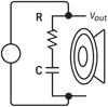 Audio engineers use low-pass filters to direct bass frequencies to subwoofers while blocking mids and highs. For example, in a speaker crossover network, this RC filter ensures only frequencies below ~154 Hz reach the bass driver. Using the calculator helps professionals quickly test different resistor and capacitor values during design, saving time and ensuring high-quality sound reproduction without distortion. Audio engineers use low-pass filters to direct bass frequencies to subwoofers while blocking mids and highs. For example, in a speaker crossover network, this RC filter ensures only frequencies below ~154 Hz reach the bass driver. Using the calculator helps professionals quickly test different resistor and capacitor values during design, saving time and ensuring high-quality sound reproduction without distortion.
R = 2.2 kΩ, C = 0.47 µF
fc = 1 / 2×π×2200×4.7×10–7 ≈ 154 Hz
3. Home / DIY: Power Supply Ripple Filtering
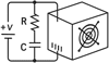 In household electronics or DIY projects, one common problem is residual AC ripple in a DC power supply. By choosing a large capacitor and small resistor, this low-pass filter attenuates unwanted ripple (usually at 50/60 Hz) while letting the DC voltage through. The calculator helps DIY hobbyists select optimal capacitor sizes, avoiding hum in audio devices, flicker in LED lights, or instability in small microcontroller projects. In household electronics or DIY projects, one common problem is residual AC ripple in a DC power supply. By choosing a large capacitor and small resistor, this low-pass filter attenuates unwanted ripple (usually at 50/60 Hz) while letting the DC voltage through. The calculator helps DIY hobbyists select optimal capacitor sizes, avoiding hum in audio devices, flicker in LED lights, or instability in small microcontroller projects.
R = 10 Ω, C = 1000 µF
fc = 1 / 2×π×10×1000×10–6 ≈ 15.9 Hz
Up
|
How to calculate capacitive reactance (Xc)? Simple examples of application |
Student Project: RC Circuit in Lab
- Data: C = 0.1 µF = 1.0×10⁻⁷ F, f = 1 kHz = 1000 Hz
- Calculation: XC = 1 / 2×π×1000×1.0×10–7 ≈ 1591 Ω
- Result / Interpretation: the capacitor provides about 1.6 kΩ reactance at 1 kHz. Helps to choose resistor values and predict circuit behavior.
Professional Use: Audio Filter
- Data: C = 0.47 µF = 4.7×10⁻⁷ F, f = 20 kHz = 20000 Hz
- Calculation: XC = 1 / 2×π×20000×4.7×10–7 ≈ 17 Ω
- Result / Interpretation: at high frequencies, the capacitor "passes" the signal (low reactance). Useful in audio crossover filters and coupling circuits.
Home / DIY: Power Supply Smoothing
- Data: C = 10 µF = 1.0×10⁻⁵ F, f = 50 Hz
- Calculation: XC = 1 / 2×π×50×1.0×10–5 ≈ 318 Ω
- Result / Interpretation: in AC ripple filtering, reactance shows how effectively a capacitor smooths voltage after rectification.
Up
|
How to select safe wire size for a 110 V Household? |
Example 1. Kitchen Appliances – Microwave + Coffee Maker
Microwave: 1200 W ÷ 110 V ≈ 11 A
Coffee machine: 800 W ÷ 110 V ≈ 7 A
Total load ≈ 18 A
If you check with the calculator using Copper, Diameter = 0.08 in (≈ AWG 12), you’ll see this wire safely supports the load.
Result: AWG 12 is correct, while AWG 14 (≈15 A limit) would be too weak.
Example 2. Small Water Heater (1500 W)
1500 W ÷ 110 V ≈ 13.6 A
Inputting Copper, Diameter = 0.064 in (≈ AWG 14) shows it can barely handle the current. The calculator confirms that moving to AWG 12 provides a safer margin.
Result: AWG 14 is at the limit, AWG 12 recommended.
Example 3. Garage Air Compressor (2000 W)
2000 W ÷ 110 V ≈ 18 A
When checking AWG 14, the calculator shows it fails (≈15 A). Switching to AWG 12 ensures the wire won’t overheat.
Result: Always size up to AWG 12 for heavy tools.
Up
|
How to select inductance for a matching LC network at 2.4 GHz with a chosen small SMD capacitor? |
Solution using the calculator:
- Click on L (calculate inductance).
- Enter C = 2.2 pF.
- Enter f = 2.4 GHz.
- Click Calculate and get result: L ≈ 2.00 nH.
Up
|
How to select a capacitor for an LC tuner circuit at 100 MHz? |
Example:
- Click on C (calculate capacitance).
- Enter L = 0.25 µH.
- Enter f = 100 MHz.
- Click Calculate and get result: C ≈ 10.13 pF.
Up
|
How to calculate the secondary current for a step-up transformer? |
Just enter primary and secondary voltages and primary current, for example:
- Primary voltage: 110 V;
- Secondary voltage: 220 V;
- Primary current: 2 A.
The calculator finds the secondary current: 1 A.
Up
|
How to calculate the secondary voltage for a step-down transformer? |
Just enter number of windings of the primary and secondary coils and primary voltage, for example:
- Primary windings: 500 turns;
- Secondary windings: 100 turns;
- Primary voltage: 230 V.
The calculator shows the secondary voltage will be 46 V.
Up
|
How to calculate breaker size for a refrigerator? |
Step 1: Gather Refrigerator Specifications
A standard household refrigerator (e.g., 20–25 ft³) typically has:
- Current Type: Single-phase
- Voltage: in the U.S. — 120 V
- Power Consumption: around 600 watts
- Safety Factor: recommended 25%–50% to account for compressor startup current
Step 2: Enter the Data in the Calculator
- System Type: Single-phase
- Voltage: 120V
- Wattage: 600W
- Safety Factor: 25% (or up to 50% for older refrigerators)
Result:
So, a 10-amp circuit breaker is suitable for a dedicated refrigerator line — which is standard for residential use in Florida.
Up
|
How to adjust variable time for off delay timer? |
Up
|
How should the circuit (Fig 2) be modified if a 12V DC motor is used? |
When using a DC motor, a diode should be used to protect the relay contacts instead of the Spark-extinguishing RC circuit. The diode should be connected in reverse polarity.
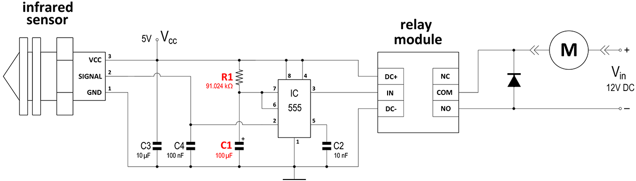
Up
|
How do I know if plugging several electrical appliances in the outlet will trip the circuit breaker? |
When you plug in multiple appliances to a circuit, the current in the circuit increases, causing the resistance to decrease and potentially overheating and tripping the circuit breaker.
To make sure that your circuit breaker does not trip, you have to use ohm's law calculator and enter known parameters to calculate the load on the circuit.
Appliances with heating elements tend to draw more power and put more load on the circuit then other.
For example an appliance with the heating element has 120V voltage and 1000W power.
On the page above choose appropriate set of values, in this case choose P/V and the selected parameters will light up blue, enter the values into the corresponding input fields and press calculate.
Using this calculator the result is 8.3A current.
That means that circuit breaker has to be rated 10A in order to operate this appliance and be able plug in another electronic device that draws no more than 1A.
Up
|
|
|
