Frequently Asked Questions

Common (2)
LCR Meters (10)
Software (24)

Oscilloscopes

  • The oscilloscope does not get a stable waveform display
  • After pressing the RUN/STOP button, the oscilloscope does not display any waveform
  • After the Acquisition is set to "Averages" or Display Persistence is set ON, the waveform refreshes slowly
  • The signal is displayed as ladder like waveform
  • How to save data to an external USB-drive?
  • How can I make an automatic calibration?
  • How can oscillogram data be saved for further reading in MS Excel?
  • How to check the availability of the specified maximum memory depth (10 Mpts per channel) in ADS-2xxxM/ADS-2xxxMV series oscilloscopes?
  • How to change language settings
  • Connecting to your device through LAN
  • How to see my Serial Number?
  • Will it measure TRUE RMS for a given waveform
  • Frozen screen or memory full
  • How to change from Chinese to English my ADS-2022 /2042 /2062 /2102 /2152
  • High voltage measurement testing are not allowed over 300 volts
  • Driver does not install or I can't find where it is located?
  • When changing the horizontal sweep on the digital oscilloscope at different horizontal points observed inexplicable change in the form of the same signal, why is this happening?
  • After the oscilloscope is powered on the display remains dark, what should I do?
  • The measured voltage amplitude value is 10 times greater or smaller than the actual value
  • After the Average value sampling is set in the Acqu Mode or the longer duration is set in the Persist in Display the display rate is slowed down
  • How to save data in a USB Flash Drive
  • Backlight adjust function is available for this HDS model
  • Backlight adjust function is not available for this HDS model
  • Unable to connect to PC or the PictBridge printer by USB
  • After the AVERAGE value sampling is set in the ACQU MODE or the longer duration is set in the DISP MODE, the display rate is slowed down
  • No Display Responses to the Push-down of RUN/STOP
  • There is wave form displayed, but it is not stable

  • The oscilloscope does not get a stable waveform display
    1. Check the Trigger Source and notice if it is set to the channel in use.
    2. Check the Trigger Type. Use "Edge" for normal signals, and use "Video" for VIDEO signals.
    3. Switch the coupling into HF Rejection or LF Rejection in order to filter the noise which disturbs trigger.
    4. Adjust the trigger Sensitivity and the hold off time.

    Up

    After pressing the RUN/STOP button, the oscilloscope does not display any waveform
    Check whether the Trigger Mode is set to "Normal" or "Single" and see whether the trigger level is out of the signal range. If yes, set the trigger level in proper range by turning the LEVEL knob or pressing the 50% button. Or set the Trigger Mode as "AUTO". Moreover, push AUTO button to display the waveform on screen.

    Up

    After the Acquisition is set to "Averages" or Display Persistence is set ON, the waveform refreshes slowly
    It is normal in these settings.

    Up

    The signal is displayed as ladder like waveform
    1. The time base setting maybe is too slow. Turn the horizontal SCALE knob to increase horizontal resolution.
    2. Maybe the display Type is set to "Vectors". Set it to "Dots" mode.

    Up

    How to save data to an external USB-drive?

    1. Press the save button on the oscilloscope control panel. The save settings menu will be available on the device screen.

    2. Use the buttons below the instrument to set the settings:

    • Type of

      Signal: Save Format - Waveform

      Settings: Save Format - Settings

      Image: Save Format – Image

      Recording: Frame-by-Frame Recorder Mode

    • A source

      Channel1

      Channel2

      Mat

      Everything.

    • Cell & Call - a call from the memory cell.
    • Storage location - USB drive.
    • Save button starts the save procedure.

    A window will open on the oscilloscope screen asking you to specify the name of the file to which the data will be saved.

    Rotate the "Multipurpose" knob to select the desired keys of the on-screen keyboard. Pressing this knob enters the selected character. After setting the file name, move the cursor to the "enter" soft key and press. The data will be written to the specified file. Further they can be viewed using the software AKTAKOM DSO-Soft6000

    Up

    How can I make an automatic calibration?

    Automatic calibration (auto-calibration) allows you to increase the precision of your oscilloscope operation when the environment temperature is changing. Auto-calibration procedure should be made to achieve the maximum precision of the oscilloscope operation in terms of the environment temperature changing of ≥ 5°C.

    To call auto calibration procedure press UTILITY and then press H1. After that use the rotary switch to select Adjust. Automatic settings menu includes the following items:

    • Self Cal – call of auto calibration procedure;
    • Default – call of factory settings (the settings recorded into the device memory).

    Auto-calibration procedure looks like as follows:

    1. Before you start auto calibration procedure it’s necessary to disconnect the probes and the cables from the oscilloscope inputs;
    2. Press UTILITY button;
    3. Press H1;
    4. Use the rotary switch to select Adjust;
    5. Press H2. You will see a message window on the oscilloscope display;
    6. Press H 2 button to launch auto calibration procedure or press any other button if you do not want to make auto calibration.


    Up

    How can oscillogram data be saved for further reading in MS Excel?
    Normally the oscilloscope allows saving files to flash memory in *.bmp and *.bin formats. To save oscillogram data for further reading in MS Excel you may use Aktakom DSO-Reader Light or Aktakom DSO-Reader Pro software which saves oscillogram data in AUL format. Saved in AUL format files can be converted (using Aktakom AULFConverter program) into *.csv format that can be read in MS Excel program. For more information refer to Aktakom AULFConverter description.

    Up

    How to check the availability of the specified maximum memory depth (10 Mpts per channel) in ADS-2xxxM/ADS-2xxxMV series oscilloscopes?

    Variant 1.

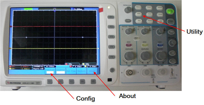
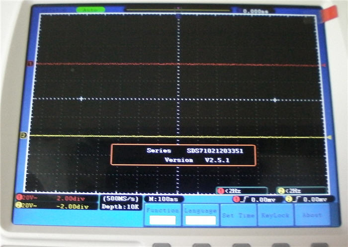
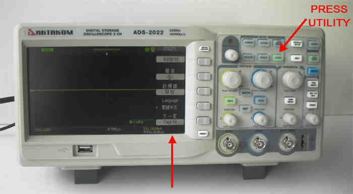
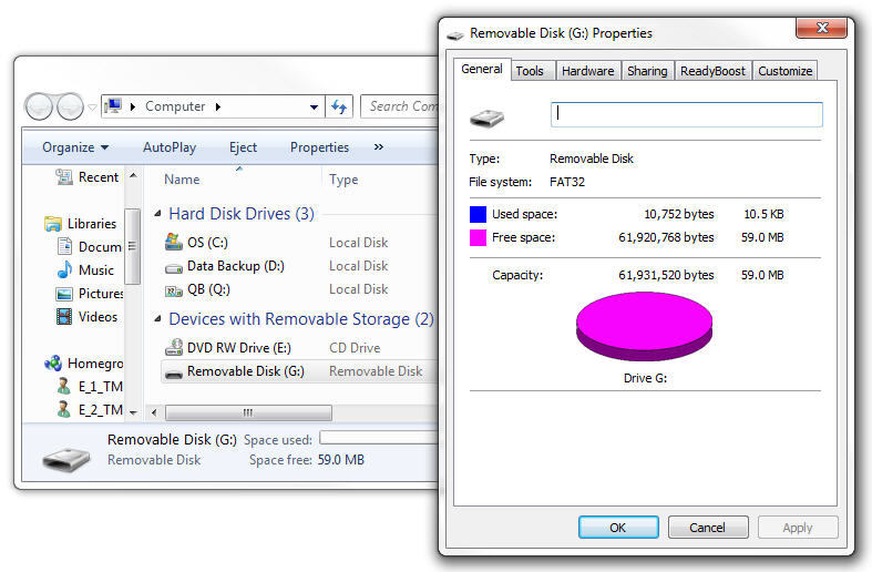
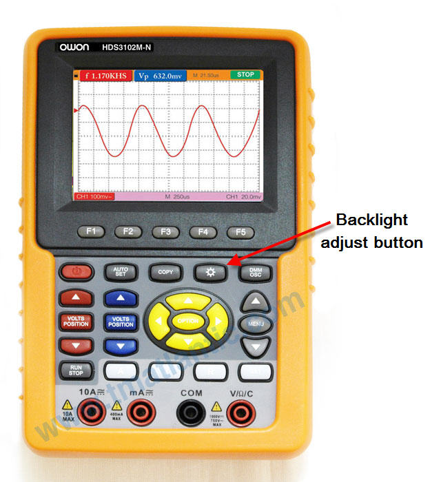
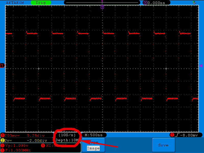
    The memory depth can be easily checked in the special area of the device screen.

    Variant 2.

    You may calculate the memory depth automatically.

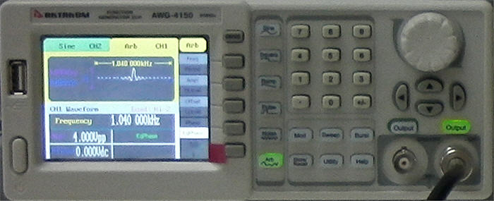
    1. Apply 1 MHz square signal from the generator to the oscilloscope

    2. Press “Auto” button of the oscilloscope to get the stable image.

    Here and further on it’s better to operate in the mode of dots signal mapping.

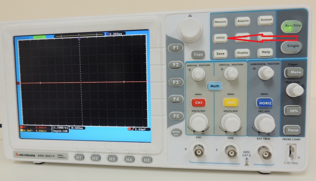
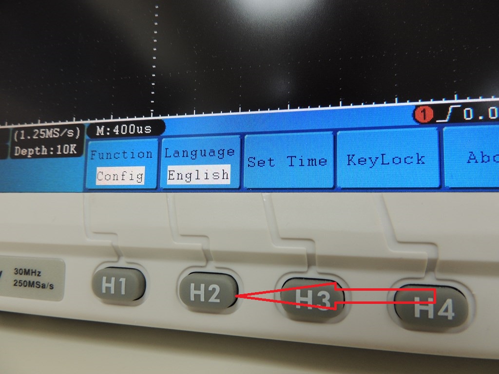
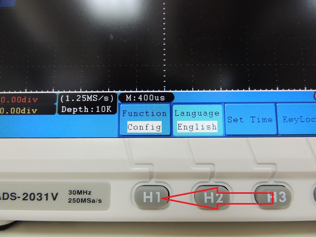
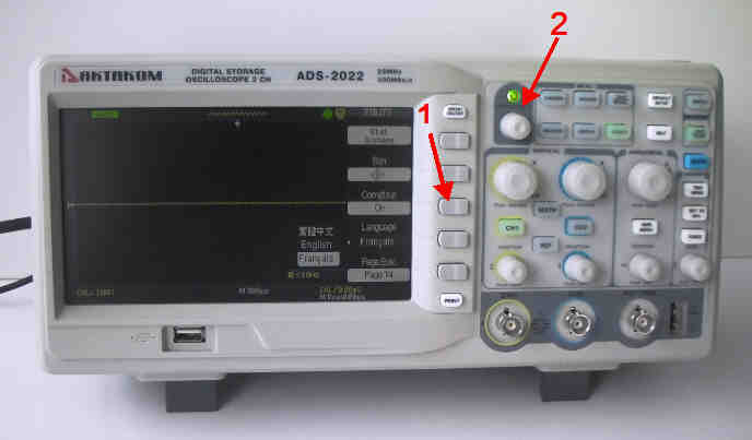
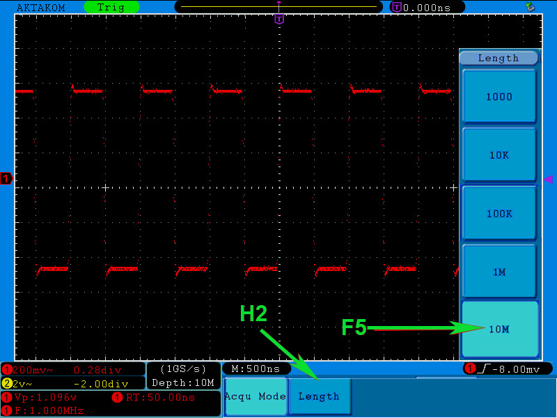
    3. Press ACQUIRE button to open the recording main menu. Then press H2 functional button to enter the mode of the memory depth specification and then press F5 to specify the memory depth of 10 Mpts.

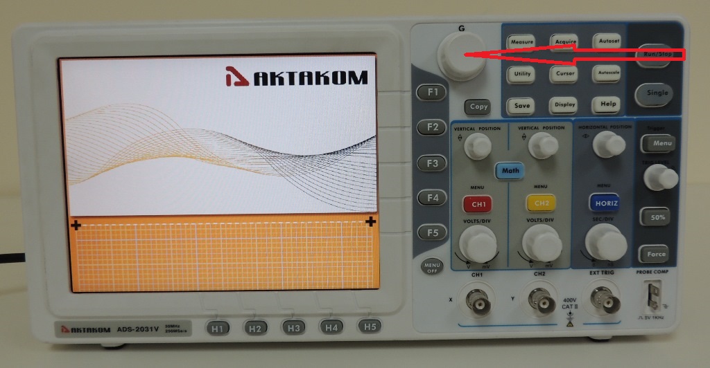
    4. Stop the signal recording. Therefore press Run/Stop button of the oscilloscope.

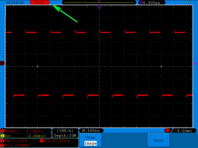
    5. Zoom in the oscillogram to see the distance between the points.

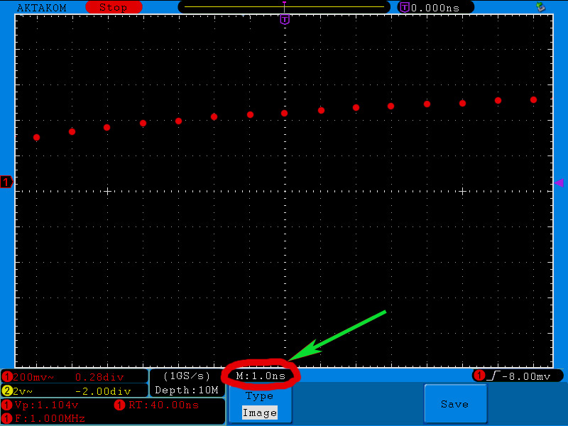
    In the image you may see that the distance between the points corresponds to 1 division. With 1 ns/div sweep the points are located in 1 ns.

    6. Afterwards set the sweep to see the whole captured signal on the display. In our case the best sweep for the whole captured signal display is 5 ms/div.

    In this case the captured signal takes 2 divisions meaning that its length is 10 ms.

    7. Now you may calculate the quantity of points which can fit in the recorded signal. Therefore divide the recorded signal length of 10 ms by the distance between the points – 1 ns.

    Namely: 10 ms/1 ns = 10 Mpts.

    Thus you may see that the specified maximum memory depth of AWG series AKTAKOM oscilloscopes is correct – 10 Mpts.

    Variant 3.

    Memory depth calculation basing on the software.

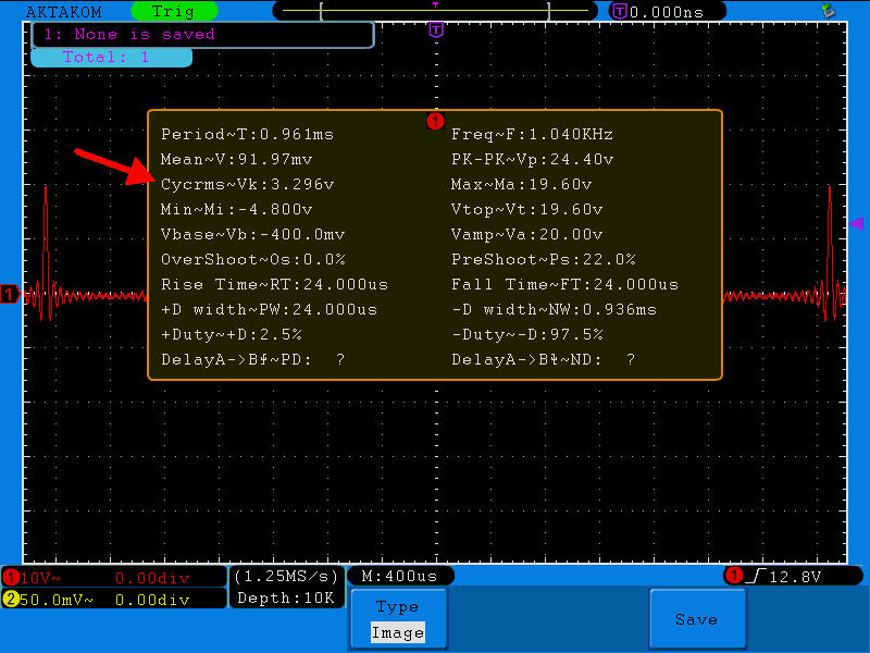
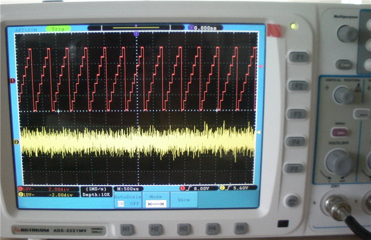
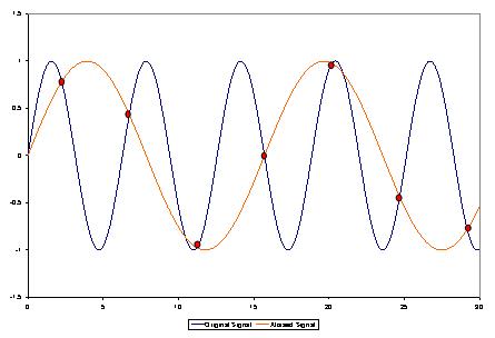
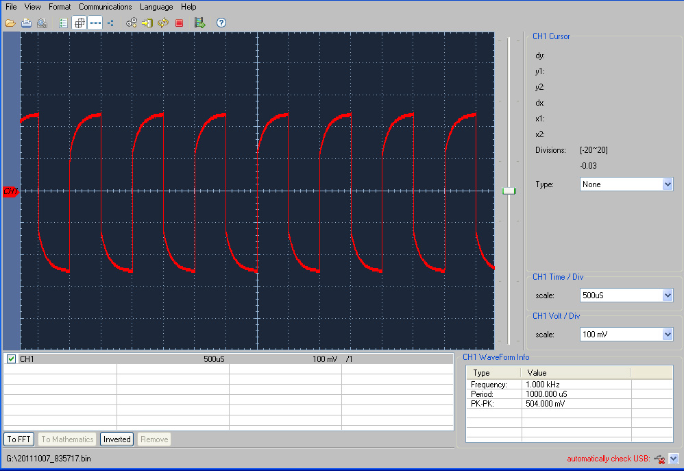
    1. Apply a signal to CHA oscilloscope input. You will see the image just like in the picture below:

    2. Connect a storage device to the USB-port. Save the data on this storage device. Therefore press COPY button. The saving process can take several seconds.

    All further data proceeding will be on your PC.

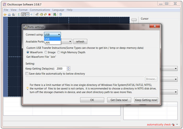
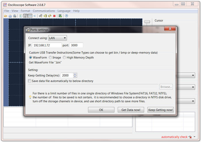
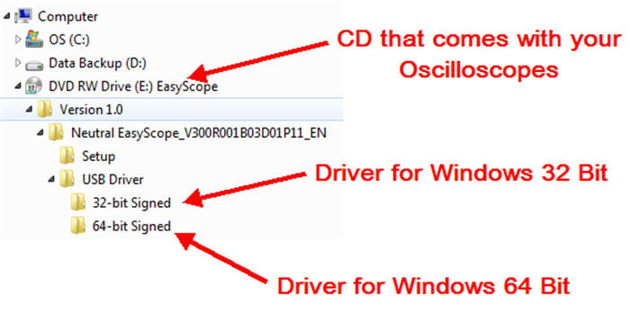
    3. In the PC program for the saved data proceeding open “File” tab and then item “Open”. Select the saved file and confirm pressing “Open” key.

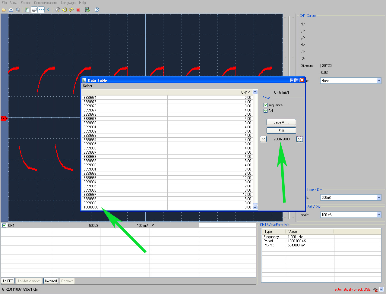
    4. Since the aim of this task is to confirm the possibility to save a signal with memory depth of 10 Mpts on the oscilloscope it means that signal data table will be much more convenient comparing to the graphics form. To show the signal as a data table click Data Table icon.

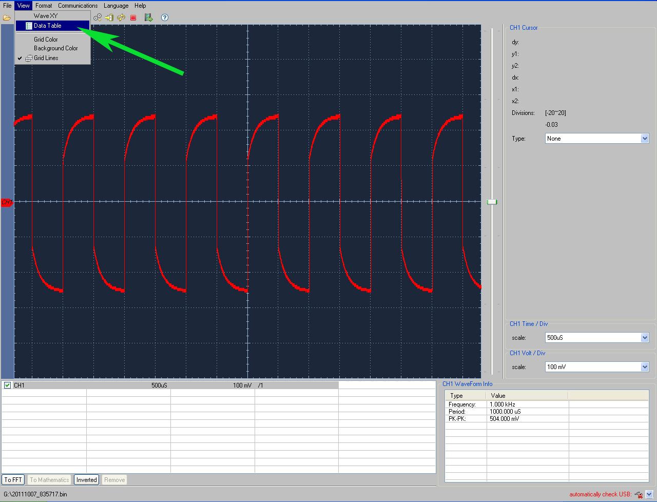
    5. You will see the oscilloscope data in a table form (pages from 1 up to 2000).

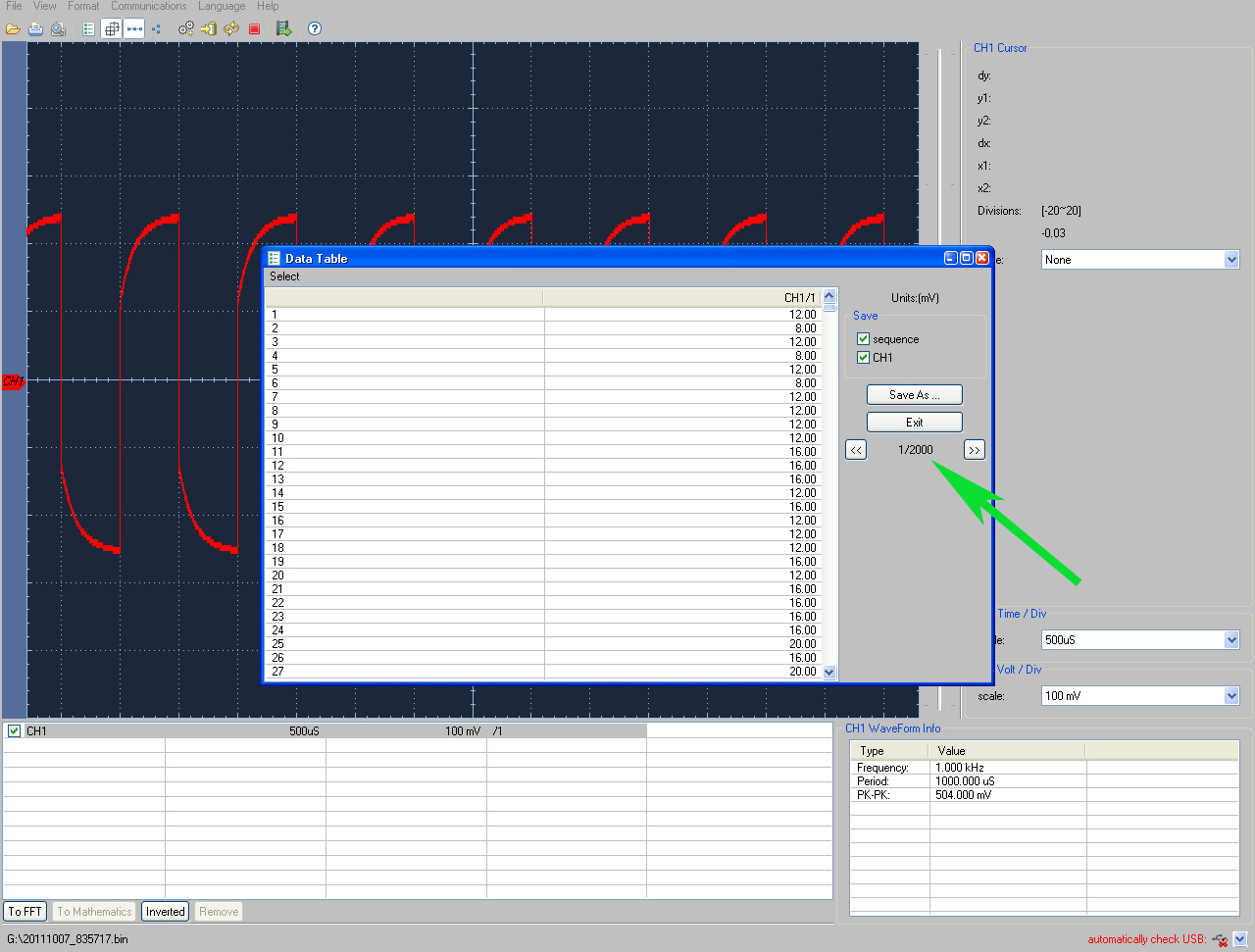
    6. By scrolling the pages up to the last one (with number 2000) you may make sure that the maximum memory depth achieves 10 Mpts/ch.


    Up

    How to change language settings

    Step 1. Turn ON Oscilloscope

    Step 2. Press UTILITY button

    Step 3. Press H2 button

    Step 4. Scroll language options using main control knob

    Step 5. Press H1 button Configure 


    Up

    Connecting to your device through LAN

    Using your DS-WAVE application software you may connect to your device through LAN. Please follow the example below

    then you will be able to type the IP you configured in your device. The factory default IP is 192.168.1.72 but if your LAN range is on a different octave please change the IP and GW in your equipment to the correct mask. The application port is 3000 please don't change it


    Up

    How to see my Serial Number?

    Your serial number is printed in a label with barcode in a back of your oscilloscope as well as in a box but if you want to confirm that number you may press the utility button and go to config (H1) and press about (H5)

    Your serial number will be display in your screen


    Up

    Will it measure TRUE RMS for a given waveform

    This is a save picture from the oscilloscope screen as per your request regarding a specific period the Cycrms signal shows a same value as Vrms in your example.

    In order to obtein that reading we use a AWG-4150 in an arbitrary wave regime. For more details go to device webpage and download PDF file at the top and go to example 6: Generate an Arbitrary Wave

    Now you may face a non-periodic signal witch is a pack of three pulse, 4 pulses, and the time between bursts is not a multiple of the pulse duration in a pack. So here the Cyrms and Vrms are different values:

    Vrms usually calculates by the signal displayed on the screen


    Cyc rms calculates for the period of the captured signal (a signal is displayed on the screen, in this case - not periodic!).

    Pk-Pk (Vp): amplitude (peak-to-peak) voltage Max (Ma): the maximum voltage
    Min (Mi): the minimum voltage
    Vtop (Vt): rectangular pulse voltage peaks
    Vbase (Vb): base voltage square wave
    Vamp (Va): voltage amplitude (Vtop - Vbase)
    Mean (V): the average value of the voltage
    Cycrms (Vk): rms voltage over one period
    Vmax-Vtop)/Vamp">Overshoot (Os): Emission measurements at the top of a percentage of the amplitude of the square wave (Vmax-Vtop) / Vamp
    Vmin-Vbase)/Vamp">Preshoot (Ps): Emission measurements at the base as a percentage of the amplitude of the rectangular pulse (Vmin-Vbase) / Vamp


    Up

    Frozen screen or memory full

    During long period of extreme oscilloscope operations with dual channel different signals the use of memory may freeze the equipment instead of switch it off so you may hold last measurement.

    Frozen screen in those cases is not a general malfunction instead you do make it run out of memory.

    Extreme use of memory is not supported for more than 5 to 10 minutes of permanent measurements


    Up

    How to change from Chinese to English my ADS-2022 /2042 /2062 /2102 /2152

    Please press the button DEFAULT SETTUP to be sure your ADS-2022 Oscilloscope is at MENU first page. You shall see same chinese symbols as shows in a picture above.

    Now press the button UTILITY to display the first menu page at the screen.

    Finally press the button #1 and choose English or a different language by using knob #2.


    Up

    High voltage measurement testing are not allowed over 300 volts

    Even when you can read in a probe 600V PK CAT I. The Aktakom, Owon or Rigol oscilloscopes does not support more than 300V RMS or 400V PK. For higher voltage please contact us to request a special device.


    Up

    Driver does not install or I can't find where it is located?

    Hereby we confirm that the Easyscope software is 32-bit and 64-bit. So if you need help do not hesitate to contact us.

    IT Department


    Up

    When changing the horizontal sweep on the digital oscilloscope at different horizontal points observed inexplicable change in the form of the same signal, why is this happening?

    In fact, this is not a problem.

    Just keep in mind that you're using a digital oscilloscope, which digitizes the signal with different sampling rates depending on the selected horizontal sweep, and then connects the digitized points with strait line while restoring the real shape of the signal.

    Your first screen shows that you are measuring voltage 50 Hz with the 10 ms / div sweep and a sampling frequency of 20 kHz Ks/s

    One signal period (20 ms), digitized in this mode, 20E-03 (sec) * 20E03 (1/sec) = 400 points. This is enough to properly restore and interpolate a sine wave of 50 Hz (i.e. in a period of 20 ms).

    Normal display, with a sweep 10 ms / div:

    Distortion of the same signal at 10 s / div sweep

    Your second screen is set to sweep 10 sec / div, and sample rate on a sweep turned to 20 samples per second (20 Sa / s). I.e. one signal period 20 ms had: 20E-03 (sec) * 20 (1/sec) = 0.4 points. That means that to restore (to interpolate the points) a sine wave with less than one point in time is impossible, so you get this mess (known as "aliasing" or a false frequency) formed by the beats of the measured frequency and sampling frequency.

    In order to correctly install a data collection in a digital oscilloscope one should follow a simple rule - the sampling rate must be at least 5-10 times higher than the frequency signal, in that case you will not have the issues that we just discussed.

    This applies to all digital oscilloscopes and in no way connected to any particular make or model of oscilloscope or its probes.


    Up

    After the oscilloscope is powered on the display remains dark, what should I do?

    Please implement the following fault treatment procedure.

    • Check whether the power cable is connected properly.
    • Ensure the power switch is turned on.
    • Restart the instrument after completing the checks above.
    • If the oscilloscope still can not work normally, please call for service.

    Up

    The measured voltage amplitude value is 10 times greater or smaller than the actual value
    Check whether the channel attenuation coefficient and the attenuation coefficient of the probe used is match.

    Up

    After the Average value sampling is set in the Acqu Mode or the longer duration is set in the Persist in Display the display rate is slowed down
    It is a normal phenomenon.

    Up

    How to save data in a USB Flash Drive

    This oscilloscope allows you to save data to an external USB Flash Drive only if the drive is formatted with FAT32.

    If you haven't noticed one huge change with Windows 7 is that FAT32 is no longer an option on formatting drives. You are now left with the options of either NTFS or exFAT. OK so your asking what is exFAT? Well its not FAT32, acutally its compatible with FAT64.

    So let's Format external USB Flash drive with FAT32 using DOS

    First you need to find what your Hard Drive is named (the label) that is easy to do right click on the hard drive and it will show you in the top box. As you can see mine has no level in the picture bellow. You also need to note which drive letter it is. Mine is Drive: G

    Next thing you need to do is to find your command prompt

    Once you get to command prompt you will need to type this:

    format /FS:FAT32 G:

    Note: You need to change the letter G to the letter of your drive

    Then just answer the questions as you like for a volume label, etc. It will take time according to the driver size.


    Now for more information of "How to Save and Recall a Waveform details" go to equipment User's Guide or find it by the following links:

    • For the ADS-2061M go to PDF page 53 (49 if printed) and do not forget that a USB Flash Drive is an external memory. See User's Guide.
    • For all other ADS models (2022, 2042M, 2061M, 2062 & M, 2102 & M, 2152 & M) go to PDF page 42 (74 if printed) See User's Guide

    Up

    Backlight adjust function is available for this HDS model

    The backlight adjust function is only available for the following HDS models:

    • HDS3102M-N
    • HDS2062M-N


    Up

    Backlight adjust function is not available for this HDS model

    The backlight adjust function is only available for the following HDS models:

    • HDS3102M-N
    • HDS2062M-N


    Up

    Unable to connect to PC or the PictBridge printer by USB
    1. When connected to PC, if the message "Unknown device" appears or prompting scanner or camera was found. Press "Utility" button to choose the I/O Setting menu, you may see the USB Device menu has been set to be "PictBridge", you should switch it to "Auto Detect" or "Computer". If necessary, restart the oscilloscope.
    2. If connecting to a PictBridge printer or the printing is unsuccessful, maybe the USB Device menu has been set to "Computer". You should switch it to "Auto Detect" or "PictBridge". If necessary, restart the oscilloscope.

    Up

    After the AVERAGE value sampling is set in the ACQU MODE or the longer duration is set in the DISP MODE, the display rate is slowed down
    It is a normal phenomenon.

    Up

    No Display Responses to the Push-down of RUN/STOP

    Check whether Normal or Signal is chosen for Polarity in the TRIG MODE menu and the trigger level exceeds the wave form range. If it is, make the trigger level is centered in the screen or set the trigger mode as Auto. In addition, with the AUTOSET button pressed, the setting above can be completed automatically.


    Up

    There is wave form displayed, but it is not stable
    • Check whether the Source item in the TRIG MODE menu is in conformity with the signal channel used in the practical application.
    • Check on the trigger Type item: The common signal chooses the Edge trigger mode for Type and the video signal the Video. Only if a proper trigger mode is applied, the wave form can be displayed steadily.
    • Try to change the trigger coupling into the high frequency suppress and the low frequency suppress to smooth the high frequency or low frequency noise triggered by the interference.

    Up

    AKTAKOM - the Best in Test Award Winner!
    Site map|Privacy policy|Terms of Use & Store Policies|How to Buy|Shipping|Payment|© T&M Atlantic, Inc., 2010-2024