| www.tmatlantic.com
Test & Soldering Equipment On-line Store |
|
D.E.V.I.C.E. (Wiki)Calculators Services |
|||||
Filter by first letter
|
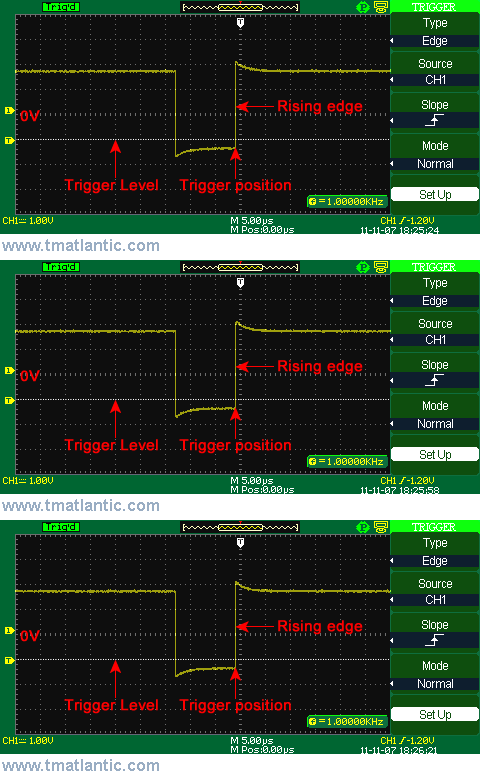
Trigger couplingTrigger coupling can be chosen depending on the signal type used for oscilloscope synchronization. The description of every coupling types is as follows: DC (direct current) – input type is open. Both constant and variable input signal components can be passed through. AC (alternating current) – Input type is closed. Only variable input signal component can be passed through. HF Reject (high-frequency filter) – signal high-frequency attenuation, attenuation of signals with high frequency, e.g. 140 KHz LF Reject (low-frequency filter) – signal low-frequency attenuation, attenuation of signals with low frequency, e.g. 7 KHz Edge triggering allows using of all coupling types acceptable. As a rule any other triggering types allow using DC input. The switching on of HF reject or LF reject allows watching low-frequency or high-frequency component of the signals under research. The picture below shows a signal oscillogram with constant component at rising edge triggering.
|
Measurement History Events
|
|
Site mapPrivacy policyTerms of Use & Store PoliciesHow to BuyShippingPayment |


