| www.tmatlantic.com
Test & Soldering Equipment On-line Store |
|
D.E.V.I.C.E. (Wiki)Calculators Services |
|||||
Filter by first letter
|
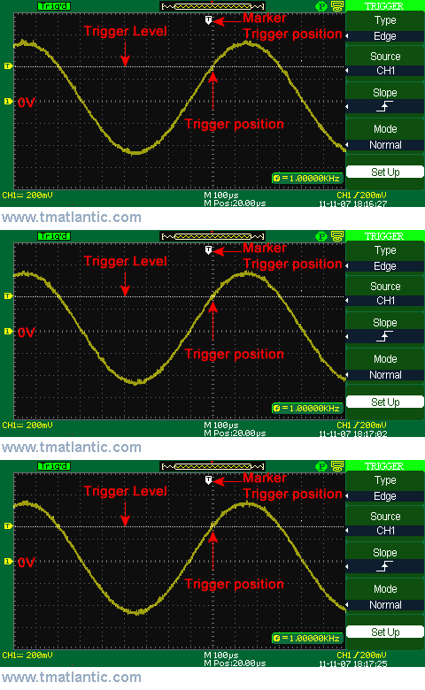
TriggerTrigger is a synchronization event which sets zero reference time value in the signal registration in digital oscilloscopes. Trigger event (trigger) result is a signal registration and an oscillogram display. All signal registration data is ordered according to the time in regard to this trigger. The oscilloscope consistently gathers and maintains the number of samples specified in the pre-trigger interval to maintain the signal part before the trigger. On the oscillogram this signal part is displayed before (closer to the left) the trigger. During the trigger the device starts registering the samples to form the signal part in the post-trigger interval. This signal part is displayed after (closer to the right) the trigger. The trigger moment index is mostly displayed at the top of the oscillogram window as a vertical marker with T letter or as an arrow (or triangle) pointing down. The picture below shows the sine signal registration oscillogram with rising edge triggering. One of the terms for the trigger forming is the trigger level excess by the input signal. The trigger position is pointed with a vertical marker with T letter.
Trigger es un evento de sincronización que establece un valor de tiempo de referencia cero en el registro de la señal en los osciloscopios digitales. El resultado del evento de disparo (disparador) es un registro de señal y una pantalla de oscilograma. Todos los datos de registro de la señal se ordenan de acuerdo con el tiempo con respecto a este disparador. El osciloscopio recopila y mantiene constantemente la cantidad de muestras especificadas en el intervalo previo al disparo para mantener la parte de la señal antes del disparo. En el oscilograma, esta parte de la señal se muestra antes (más cerca a la izquierda) del disparo. Durante el disparo, el dispositivo comienza a registrar las muestras para formar la parte de la señal en el intervalo posterior al disparo. Esta parte de la señal se muestra después (más cerca a la derecha) del disparador. El índice del momento de disparo se muestra principalmente en la parte superior de la ventana del oscilograma como un marcador vertical con la letra T o como una flecha (o triángulo) apuntando hacia abajo. La siguiente imagen muestra el oscilograma de registro de señal sinusoidal con disparo de flanco ascendente. Uno de los términos para la formación del disparo es el exceso del nivel de disparo por la señal de entrada. La posición del gatillo se señala con un marcador vertical con letra T.
|
|
Site mapPrivacy policyTerms of Use & Store PoliciesHow to BuyShippingPayment |


