| www.tmatlantic.com
Test & Soldering Equipment On-line Store |
D.E.V.I.C.E. (Wiki)Calculators Services |
||||||
Filter by first letter
|
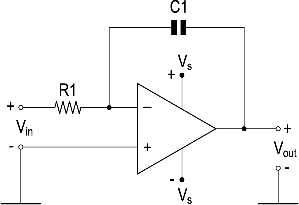
IntegratorAn operational amplifier-based integrator is most often built on the basis of an inverting amplifier and is shown in Fig. 1.
The integrator circuit at the output produces an inverted voltage Vout numerically equal to the integral Vin over time t. The value of the output voltage (Vout) taking into account the voltage at time t=0 (Vst) is determined by the formula:
It is important to take into account that an operational amplifier-based integrator ceases to be a DC amplifier, since negative feedback is implemented through a capacitor with infinitely large DC resistance. Integrators are used in various systems that require calculating an integral (usually over time). Among them are devices for monitoring and accounting for the consumption of liquids, gas, and many others. The operational amplifier based integrator circuit should also be considered as a low-pass filter (LPF) used in sound reproduction, radio transmitting and radio receiving equipment. If you feed a steady, symmetrical square wave into the integrator, the constant positive and negative voltage plateaus integrate into linear positive and negative ramps. This produces a clean triangle wave at the output, which is highly useful in PWM generators and synthesizer sub-circuits. Use our online Integrator Calculator Frequently Asked QuestionsWhat happens if a constant DC voltage is applied to an ideal op amp integrator? If you feed a steady DC voltage (Vin) into an ideal integrator, the circuit will calculate a continuous, linear mathematical accumulation, causing the output voltage to form a steady ramp Vout = -Vin × t / RC. In a real physical circuit, this ramp cannot climb forever; it will quickly hit the op-amp's power supply saturation rails (+Vs or -Vs) and flatten out, stopping any further integration.
Why do real-world op amp integrators require a large resistor in parallel with the feedback capacitor? Real-world operational amplifiers suffer from internal imperfections called input bias currents and input offset voltages. Even with 0 V on the input, these tiny errors act as a permanent DC input signal. Over time, the capacitor integrates this error until the op-amp saturates (drifts to the power rail), rendering the circuit useless. Placing a massive resistor in parallel with the capacitor provides a safe DC discharge path that stabilizes the circuit at low frequencies, transforming it into a practical Lossy Integrator.
How does the integration time constant (RC) affect the output signal's slope? The time constant τ = RC is inversely proportional to the circuit's integration speed. If you choose small values for R and C, the 1/(RC) multiplier becomes large, causing the output voltage ramp to shoot up incredibly fast (steep slope). If you choose massive values for R and C, the integration slows down drastically, resulting in a very gentle, slow-moving output slope.
What is the difference between an op amp differentiator and an op amp integrator? The two circuits perform inverse mathematical operations by swapping the physical positions of the resistor and capacitor. An integrator uses an input resistor and a feedback capacitor to calculate the cumulative area under the signal curve over time, which smooths out sharp transitions (e.g., turning square waves into triangle waves). A differentiator uses an input capacitor and a feedback resistor to calculate the instantaneous rate of change of the signal, which sharpens edges and detects transitions (e.g., turning square waves into sharp spikes).
|
Measurement History Events
Units Converter
|


|