| www.tmatlantic.com
Test & Soldering Equipment On-line Store |
|
D.E.V.I.C.E. (Wiki)Calculators Services |
|||||
Filter by first letter
|
Capacitor
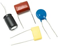
A capacitor in electronic circuits is a passive component of an electrical circuit designed to store electrical energy and implement filtering or create internal communication. The electrical characteristics of a capacitor are determined by its design and the properties of the materials used. Capacitors used in electronic circuits come with wire leads and SMD(Surface Mount Device). For ease of marking, manufacturers group capacitors into series or rows: E6, E12, E24, etc. - depending on accuracy. Also, depending on the design of the capacitor and the type of dielectric, capacitors have different operating voltages. Capacitors are classified into different types depending on the dielectric material used: • Ceramic capacitor, sometimes called multilayer ceramic capacitor • Tantalum capacitor • Electrolytic capacitor Leaded capacitors are often marked with a color code that depends on the design of the capacitor
To determine capacitor value by color coding please use our Capacitor Color Code Calculator. • SMD Capacitors are manufactured as a multilayer ceramic capacitor Where ceramic is used as the dielectric material. These capacitors are based on the electrical properties of ceramics. Because the properties of ceramics are multidimensional. The ceramic used in the capacitor allows the capacitor to be smaller in size compared to other types. Ceramic capacitors use various ceramic dioxides such as titanium dioxide, barium strontium, barium titanate, etc. One of the important characteristics of a capacitor is the temperature coefficient of capacitance, which in an SMD capacitor can be achieved using various ceramic dielectric materials. The dielectric insulation of this capacitor can be achieved by using various layers of ceramics used between the two conductors. Typically, its electrodes are coated with silver, which provides excellent soldering properties of this capacitor. SMD Capacitors are marked based on a 3 character code More information about Capacitance is available in the D.E.V.I.C.E. Two-character marking code for small capacitorsFor capacitances following the E3, E6, E12 or E24 series of preferred values, the former ANSI/EIA-198-D:1991, ANSI/EIA-198-1-E:1998 and ANSI/EIA-198-1-F:2002 as well as the amendment IEC 60062:2016/AMD1:2019 to IEC 60062 define a special two-character marking code for capacitors for very small parts which leave no room to print the above mentioned three- / four-character code onto them. The code consists of an uppercase letter denoting the two significant digits of the value followed by a digit indicating the multiplier. The EIA standard also defines a number of lowercase letters to specify a number of values not found in E24.
RKM codeThe notation to state a capacitor's value in a circuit diagram varies. The RKM code following IEC 60062 and BS 1852 avoids using a decimal separator and replaces the decimal separator with the SI prefix symbol for the particular value (and the letter F for weight 1). The code is also used for part markings. Example: 4n7 for 4.7 nF or 2F2 for 2.2 F. To determine capacitor value by color coding please use our Capacitor Color Code Calculator.
|
|||||||||||||||||||||||||||||||||||||||||||||||||||||||||||||||||||||||||||||||||||||||||||||||||||||||||||||||||||||||||||||||||||||||||||||||||||||||||||||||||||||||||||||||||||||||||||||||||||||||||||||||||||||||||||||||||||||||||||||||||||||||||||||||||||||||||||||||||||||||||||||||||||||||||||||||||||||||||||||||||||||||||||||||||||||||||||||||||||||||||||||||||||||||||||||||||||||||||||||||||||||||||||||||||||||||||||||||||||||||||||||||||||||||||
|
Site mapPrivacy policyTerms of Use & Store PoliciesHow to BuyShippingPayment |


