| www.tmatlantic.com
Test & Soldering Equipment On-line Store |
D.E.V.I.C.E. (Wiki)Calculators Services |
||||||
Filter by first letter
|
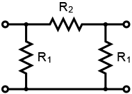
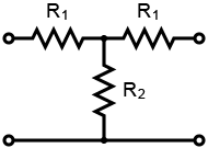
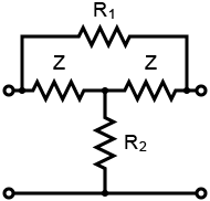
Pi Attenuator, T Attenuator and bridged T Attenuator CalculatorThis online calculator allows you to quickly determine the value of resistors in a Pi attenuator (Fig. 1), T attenuator (Fig. 2) or bridged T attenuator (Fig. 3) circuit. Just enter the desired attenuation (in dB) and impedance (Z) to calculate the needed resistors (R1 and R2) values.
This tool uses the following equations for Pi attenuator:
K = 10(attenuation / 20) This tool uses the following equations for T attenuator:
K = 10(attenuation / 20) This tool uses the following equations for bridged T attenuator:
K = 10(attenuation / 20) For RF applications, use precision resistors and consider frequency-dependent parasitics. Learn more about SMD resistor code. You might also find helpful: dB Gain Calculator Frequently Asked QuestionsWhy engineers need the Pi, T & Bridged-T Attenuator Calculator?Attenuators are not "just resistors" — they are precision impedance-controlled networks. This calculator allows engineers to instantly design Pi, T, and Bridged-T attenuators with correct impedance matching and exact attenuation levels, saving time and preventing costly signal integrity mistakes. Engineers use this calculator to:
Whether you work in RF, audio, test & measurement, or electronics education, this calculator turns theory into ready-to-build resistor values. Practical Use CasesRF & Microwave EngineeringAn RF engineer needs a 10 dB attenuator for a 50 Ω signal path between a signal generator and spectrum analyzer. The calculator provides exact resistor values for Pi or T topology, ensuring:
Test & Measurement LabsA lab technician must reduce signal amplitude before feeding a high-gain amplifier. Using the Bridged-T attenuator, they achieve:
Electronics Education & TrainingStudents learning analog electronics use the calculator to:
What is the difference between Pi and T attenuators? Pi attenuators use two shunt resistors and one series resistor, while T attenuators use two series resistors and one shunt resistor. Both provide identical attenuation but differ in physical layout and power handling.
When should I use a Bridged-T attenuator? Use a Bridged-T attenuator when you need variable attenuation while maintaining constant impedance, commonly in RF test equipment and audio controls.
Can this calculator be used for RF applications? Yes. The calculator is suitable for RF, audio, and general signal applications, assuming resistor tolerances and frequency limits are properly selected.
Does attenuation affect impedance matching? Incorrect resistor values will affect impedance matching. This calculator ensures proper matching at both input and output, preventing signal reflections.
|
Measurement History Events
Units Converter
|


|