| www.tmatlantic.com
Test & Soldering Equipment On-line Store |
D.E.V.I.C.E. (Wiki)Calculators Services |
||||||
Filter by first letter
|
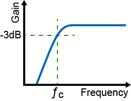
High Pass Filter CalculatorDesigning an audio crossover, stripping sub-bass rumble from a microphone signal, or isolating high-frequency carriers in RF systems requires a predictable attenuation slope. This interactive High-Pass Filter (HPF) Calculator computes the exact cutoff frequency (-3dB point) based on your selected resistor (R) and capacitor (C) or indictor (L) values, or reverses the math to help you find the required component values for a target frequency.
This calculator allows you to choose filter circuit: RC filter or RL filter. RC high pass passive filterThe RC high pass passive filter consists of a capacitor placed in series with the signal path, followed by a resistor shunted to ground. Because capacitive reactance decreases as frequency rises, high-frequency signals pass through with minimal attenuation, while low frequencies are blocked. Cutoff frequency formula: fc = 1 / 2πRC At the exact cutoff frequency (fc), the output voltage drops to approximately 70.7% of the input voltage, which corresponds to the -3dB half-power point. Below this frequency, a first-order filter attenuates the signal at a steady rate of 6dB per octave (or 20dB per decade). To calculate a particular parameter of a circuit (e.g. cutoff frequency (fc), resistance (R) value or capacitance (C) value) click on the corresponding parameter on the figure and then enter all the necessary values:
RL high pass passive filterThe RL high pass passive filter consists of a resistor placed in series with the signal path, followed by an inductor shunted to ground. Cutoff frequency formula: fc = R / 2πL To calculate a particular parameter of a circuit (e.g. cutoff frequency (fc), resistance (R) value or inductance (L) value) click on the corresponding parameter on the figure and then enter all the necessary values:
When moving from this calculator to hardware prototyping, pay close attention to component tolerances. Standard ceramic capacitors can vary by up to ±20%, which will visibly shift your actual cutoff frequency. For precision audio or RF filtering, opt for film or C0G/NP0 ceramic capacitors and 1% metal-film resistors to keep the physical circuit behavior aligned with your calculated simulation data. To determine the cutoff frequency and other parameters of a low pass passive filter use our online Low Pass Filter Calculator. We also provide online tools to calculate capacitive reactance and inductive reactance. Frequently Asked QuestionsWhat happens to the signal below the cutoff frequency in a high-pass filter? Below the cutoff frequency, the filter enters its "stopband" region, where it continuously attenuates incoming signals. For a standard first-order passive RC filter, the signal drops at a fixed slope of 20dB per decade (or 6dB per octave). If you require a much steeper drop to aggressively eliminate low-frequency interference, you must cascade multiple stages together to build a second-order (12dB/oct) or fourth-order (24dB/oct) active filter network.
Why is the cutoff frequency of a filter called the -3dB point? The -3dB designation represents the half-power point of the circuit. At this specific frequency, the output power drops to exactly 50% of the input power, and the output voltage drops to 1/√2 (approximately 70.7%) of the input voltage. It serves as the universal engineering standard to mark the boundary line between a filter's passband (allowed frequencies) and stopband (blocked frequencies).
How do I choose the resistor and capacitor values for an audio high-pass filter? When selecting component values, you must balance the input impedance of the next stage in your audio chain. If your resistor value (R) is set too low, it will excessively load down the audio source, causing distortion. A standard practice in line-level audio design is to keep the resistor value between 10kΩ and 100kΩ, and then use this calculator to solve for the exact matching capacitance (C) needed to clear out low-frequency mud or DC offsets.
What is the difference between a passive high-pass filter and an active high-pass filter? A passive high-pass filter relies entirely on unpowered components (resistors, capacitors, or inductors). While simple and cost-effective, passive filters always introduce a slight insertion loss and cannot amplify a signal. An active high-pass filter combines these passive elements with an operational amplifier (op-amp). This configuration provides isolation, prevents impedance loading bugs, allows for adjustable gain, and makes it easy to construct complex high-order filter slopes without losing signal strength.
|
Measurement History Events
Units Converter
|


|