| www.tmatlantic.com
Test & Soldering Equipment On-line Store |
|
D.E.V.I.C.E. (Wiki)Calculators Services |
|||||
Filter by first letter
|
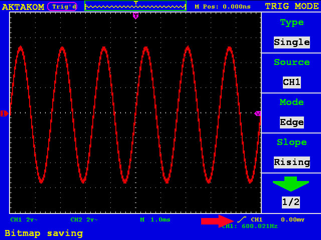
Edge-triggered synchronizationAn edge trigger occurs when the input signal crosses the specified voltage level in the chosen direction. Depending on the functionality of oscilloscope capabilities the trigger can occur on rising, falling or rising & falling edge. The conditions for the trigger is the edge direction, the trigger source, trigger level is usually shown at the bottom of the screen. Thus the following picture shows the rising edge trigger, the trigger source is CH1 channel, the trigger level = 0 V:
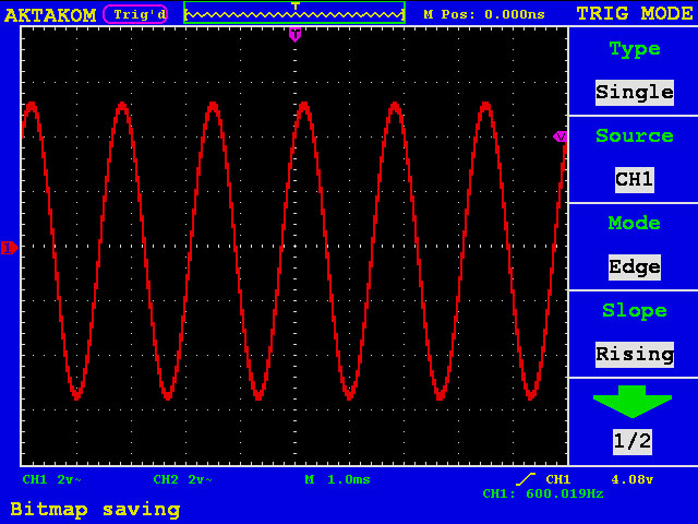
The next picture shows the rising edge trigger, the trigger source is CH1, the trigger level is 4.08 V:
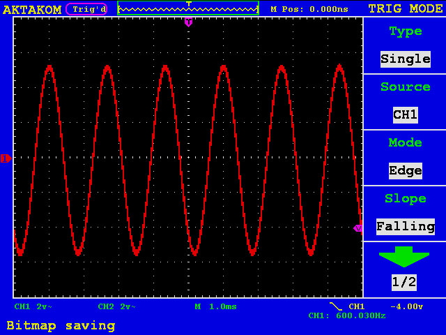
In the picture below you can see the falling edge trigger, the trigger source is CH1 channel, the trigger level = 0 V:
This is the most widespread variant of synchronization. |
|
Site mapPrivacy policyTerms of Use & Store PoliciesHow to BuyShippingPayment |


