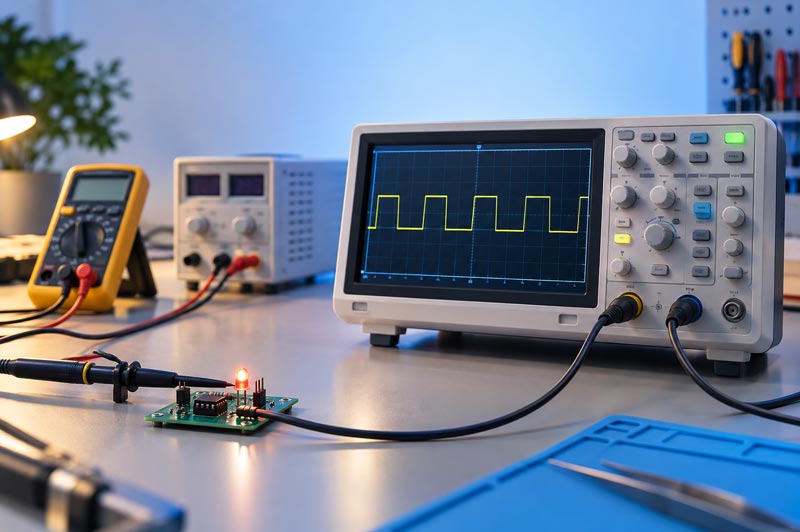
This course teaches participants to acquire a trustworthy waveform, measure low-voltage signals, and locate faults by comparing expected and observed signals at test points.
Objective and audience
This course is intended for students, entry-level electronics repair technicians, and users who can already measure voltage and resistance and check continuity with a digital multimeter. Familiarity with basic components and circuits is helpful; EE-3 and EE-6 provide useful preparation.
Proposed format
Ten 90-minute lessons, totaling 15 instructional hours. Approximately one-third of each lesson is explanation and demonstration; the remainder is hands-on measurement and review. Instructor-led lab sessions or remote sessions are possible if participants have an approved equipment set. Exercises use prechecked, low-voltage training circuits with accessible test points.
Learning outcomes
By the end of the course, participants will be able to:
- Verify a safe ground reference and select a suitable probe.
- Match probe attenuation to the channel setting and configure voltage and time scales.
- Stabilize a repetitive waveform and capture a single event.
- Measure amplitude, period, frequency, duty cycle, and time delay while documenting the measurement method.
- Distinguish a possible circuit fault from a connection or instrument setup error.
- Compare signals across test points and produce a supported troubleshooting conclusion.
Lesson plan
- Applications and safety:
Inspect the oscilloscope, probes, and training circuit; identify the ground reference; draw a safe connection plan.
- Probes and first waveform:
Match the 1×/10× probe setting to the channel; check and compensate the probe using the instrument's probe-adjustment output if provided; capture a square wave.
- Voltage and time scales:
Configure V/div, s/div, zero position, and AC/DC coupling; compare a useful display with a scaling error.
- Triggering and capture:
Select trigger source, level, and edge; use Auto, Normal, and Single where supported; capture one pulse and document trigger settings.
- Waveform measurements:
Use cursors and automatic measurements for Vpp, period, frequency, pulse width, and duty cycle; compare manual and automatic readings.
- Two-channel comparison:
Compare input and output on a low-voltage filter or training amplifier stage; measure delay; check channel ground connections before probing.
- Noise and measurement limits:
Compare long and short probe ground connections, bandwidth limiting if supported, and sampling choices; explain possible measurement artifacts.
- Power and PWM case studies:
Examine a low-voltage supply output and an LED module's PWM control signal; compare expected and observed behavior without probing the mains-connected section.
- Troubleshooting method:
Diagnose an instructor-inserted fault on a low-voltage training board; plan DMM and oscilloscope checks, record test-point readings, and consider alternative causes.
- Final exercise:
Independently diagnose a second training fault; submit waveforms, instrument settings, an observation table, and a conclusion.
Equipment for exercises
- A two-channel digital oscilloscope with compatible working probes and basic measurement and trigger functions; select the model when the course is approved.
- A digital multimeter for preliminary circuit and supply checks.
- A current-limited low-voltage bench supply, training board, and signal generator or board with a known test signal.
- Short leads and manufacturer-approved probe accessories; a computer or storage device if the oscilloscope supports waveform export.
Safety and scope
On a typical bench oscilloscope, a probe's ground reference is normally connected to protective earth through the instrument. Check the specific model's documentation and the circuit test point before connecting it. Never defeat the oscilloscope's protective earth connection to make a measurement, and never attach the probe ground clip to an arbitrary point in a mains-connected, floating, or high-voltage circuit. Measuring mains voltage, the primary side of a switching power supply, and building wiring is outside this course's hands-on scope. Such work requires separate training and suitable measurement equipment.
Final assessment
The final exercise is complete when the participant:
- demonstrates a safe connection,
- records readable waveforms at a minimum of two test points,
- documents probe attenuation, scales, trigger settings, and measurement method,
- compares observations with the expected circuit behavior,
- states what the measurements establish and what remains untested.
Completion documents performance on the course exercises; this proposal does not claim a formal certification or professional qualification.
Sources and technical references
Back to the section
|