| www.tmatlantic.com
Test & Soldering Equipment On-line Store |
|
D.E.V.I.C.E. (Wiki)Calculators Services |
|||||
Filter by first letter
|
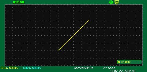
X-Y ModeX-Y mode is a specialized two-channel mode of oscilloscopes when the signal of channel 1 is used for the deviation along the horizontal axis (X) and the signal of channel 2 – along the vertical axis (Y). X-Y mode allows displaying the dependence of one physical process (Y signal) on the other one (X signal). For example the dependence of gas pressure in a fixed volume on the temperature of this gas. Therefore it’s necessary to convert the signals of both processes into appropriate voltage signals for their transfer to the oscilloscope inputs. A simple example of this mode use in the measuring technology is the ratio measurement of two sine signal parameters of two generators with the help of Lissajous figures. These figures forms help to identify signal frequencies ratio, their amplitude and the phase shift of one signal relative to the other one. Let’s analyze X-Y mode by the example of the work on Aktakom ADS -Series digital wide screen oscilloscope. In the simplest case then the signal frequencies of both channels are equal Lissajous figures are displayed as ellipses. Then the phase difference is 0 or π these ellipses degenerate into line segments. If the signal ranges are equal the inclination angle of these figures to the axis is 45 degrees.
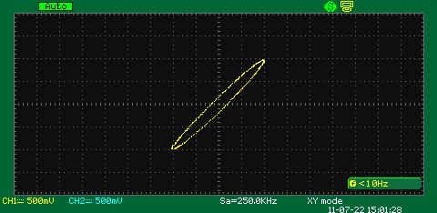
If for example, the phase difference is π/2, then the signal ranges are equal, the segments turn to be a circle. If the signal phases don’t coincide the oscilloscope displays ellipse. On the screenshot below the signal phase difference in channel 1 and channel 2 is 10 degrees.
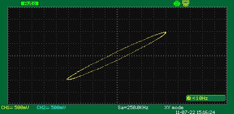
The inclination angle of the ellipse can provide the information about the signal voltages for each channel. Thus the screenshot below shows the example when the signal phase difference for each channel is 10 degrees and the ranges differ from each other twice.
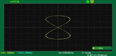
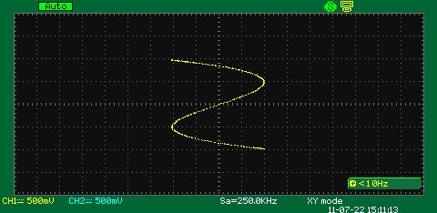
When the frequencies are close but not the same Lissajous figure is rotating on the oscilloscope display. The rotation period is the reciprocal value to the frequencies difference. For example if the rotation period is 5 seconds the signal frequency difference between the channels is 0.2 Hz. X-Y mode can be also used for the analysis of multiple frequencies. The example below shows the situation when the signal frequencies of channel 1 and 2 differ from each other twice, the phase difference is 0 degree.
The same happens when the signal frequencies of channel 1 and 2 differ from each other three times, the phase difference is 0 degree as well.
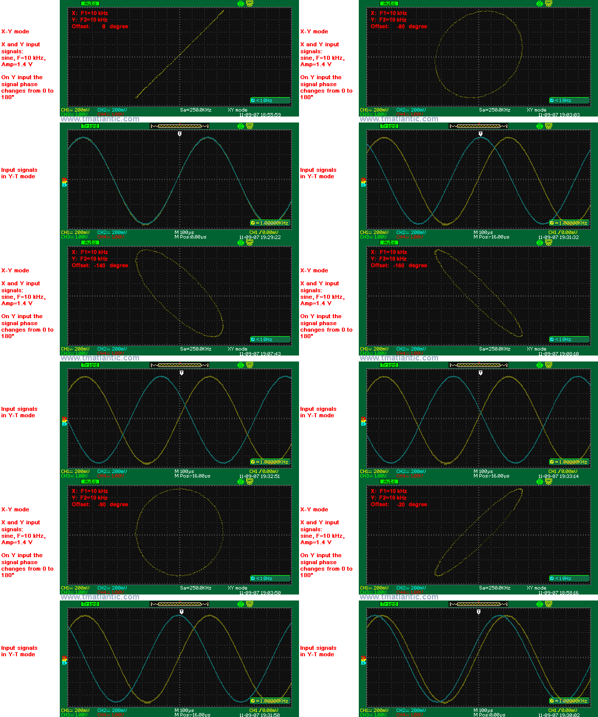
There are animated pictures below that demonstrate the examples of Lissajous figures for a case when signal amplitudes and frequencies are equal, only phase shift stays changeable. The figure is represented as an ellipse which changes its form from a straight line when there are phase shifts equaled to 0 and 180 degrees to a circle when the phase shift equals 90 and 270 degrees.
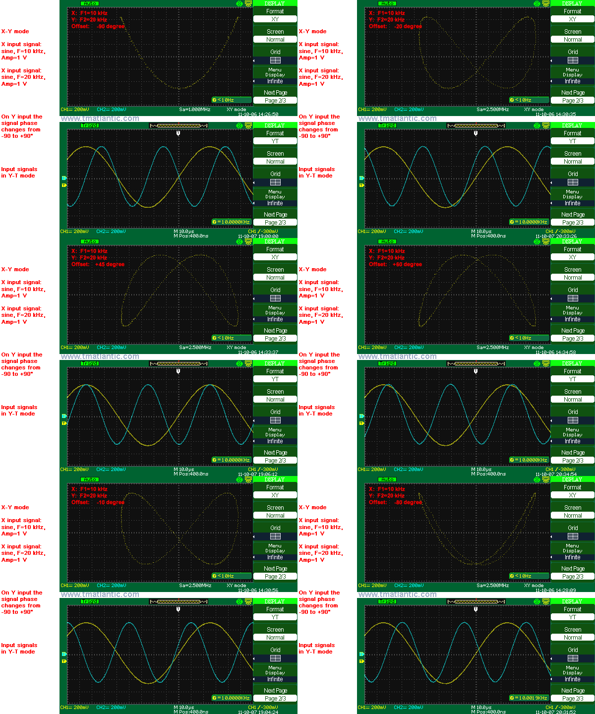
And also for those cases when the amplitudes are equal and the signal frequencies differ from each other twice and also only the phase shift is changeable.
At other frequencies ratios the figure form will be different and it can help to identify this ratio. |
Measurement History Events
Units Converter
|
|
Site mapPrivacy policyTerms of Use & Store PoliciesHow to BuyShippingPayment |


