| www.tmatlantic.com
Test & Soldering Equipment On-line Store |
D.E.V.I.C.E. (Wiki)Calculators Services |
||||||
Filter by first letter
|
Low Pass Filter CalculatorExtracting a clean DC voltage from a PWM signal, removing high-frequency hiss from an audio line, or preventing aliasing before an Analog-to-Digital Converter (ADC) requires predictable signal attenuation. This interactive Low-Pass Filter (LPF) Calculator computes the exact cutoff frequency (-3dB point) based on your resistor (R) and capacitor (C) or inductor (L) values, and works in reverse to help you determine target component values.
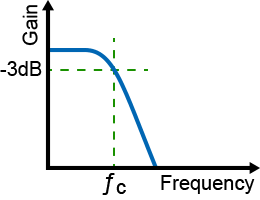
This calculator allows you to choose filter circuit: RC filter or RL filter. RC low pass passive filterThe RC low pass passive filter consists of a resistor placed in series with the signal path, followed by a capacitor shunted to ground. At low frequencies, the capacitor's reactance is exceptionally high, allowing the signal to pass straight to the output. As the frequency increases, the capacitive reactance drops, shunting high-frequency noise safely to ground. Cutoff frequency formula: fc = 1 / 2πRC At this calculated fc threshold, the output signal power drops to exactly 50% (the -3dB half-power point). Frequencies climbing past this point enter the stopband, where they are attenuated at a steady slope of 6dB per octave (20dB per decade). To calculate a particular parameter of a circuit (e.g. cutoff frequency (fc), resistance (R) value or capacitance (C) value) click on the corresponding parameter on the figure and then enter all the necessary values:
RL low pass passive filterThe RL low pass passive filter consists of an inductor placed in series with the signal path, followed by a resistor shunted to ground. Cutoff frequency formula: fc = R / 2πL To calculate a particular parameter of a circuit (e.g. cutoff frequency (fc), resistance (R) value or inductance (L) value) click on the corresponding parameter on the figure and then enter all the necessary values:
When building a real-world low-pass filter, component selection shapes your circuit's thermal stability. Standard carbon composition resistors and general-purpose ceramic capacitors fluctuate with temperature shifts, causing the physical cutoff frequency to drift. For sensitive signal-conditioning tasks, use low-noise metal-film resistors combined with film or stable C0G/NP0 ceramic capacitors. Frequently Asked QuestionsHow do you use an RC low-pass filter to smooth a PWM signal into DC voltage? A PWM (Pulse-Width Modulation) signal transitions rapidly between high and low digital states. An RC low-pass filter acts as an integrator; by choosing a cutoff frequency (fc) significantly lower than the PWM switching frequency, the capacitor blocks the fast AC switching edges and charges up to the average value of the duty cycle. This converts the digital pulses into a clean, stable analog DC voltage rail.
What is the difference between a first-order and a second-order low-pass filter? The primary difference is the aggressiveness of the attenuation slope in the stopband. A first-order filter uses one resistor and one capacitor, yielding an attenuation slope of 20dB per decade (6dB per octave). A second-order filter cascades two RC stages together (or utilizes an active op-amp topology), doubling the roll-off sharpness to 40dB per decade (12dB per octave) to isolate target signals more effectively.
Why is a low-pass filter necessary before an Analog-to-Digital Converter (ADC)? In digital signal processing, an input low-pass filter is mandatory to serve as an anti-aliasing filter. According to the Nyquist-Shannon sampling theorem, an ADC cannot accurately sample any signal frequency that exceeds half of its sampling rate (fs/2). Without a low-pass filter to aggressively choke off those ultra-high frequencies before conversion, they will "fold back" into the lower frequency spectrum, generating permanent digital distortion known as aliasing.
Does a passive low-pass filter affect the input impedance of a circuit? Yes. The total impedance of an RC low-pass filter drops as the signal frequency climbs because the capacitor's reactance falls toward zero. At high frequencies, the input source sees an impedance that effectively equals just the value of the resistor (R) shorted to ground. If R is set too low, it can overload the preceding amplifier stage, dragging down signal amplitude and introducing unwanted harmonic distortion.
How to Calculate the Cutoff Frequency of a Low-Pass Filter? Simple Examples1. Student Project: Signal Filtering in Lab
R = 1 kΩ, C = 0.1 µF fc = 1 / 2×π×1000×1.0×10–7 ≈ 1592 Hz 2. Professional Use: Audio Crossover
R = 2.2 kΩ, C = 0.47 µF fc = 1 / 2×π×2200×4.7×10–7 ≈ 154 Hz 3. Home / DIY: Power Supply Ripple Filtering
R = 10 Ω, C = 1000 µF fc = 1 / 2×π×10×1000×10–6 ≈ 15.9 Hz |
Units Converter
|


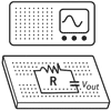 In a basic electronics lab, students often need to analyze how a simple RC filter affects signals of different frequencies. With this setup, signals below ~1.6 kHz pass almost unchanged, while higher frequencies are attenuated. This helps students visualize frequency response, understand the concept of cutoff frequency, and prepare for more complex filter designs in advanced courses.
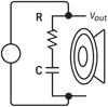 Audio engineers use low-pass filters to direct bass frequencies to subwoofers while blocking mids and highs. For example, in a speaker crossover network, this RC filter ensures only frequencies below ~154 Hz reach the bass driver. Using the calculator helps professionals quickly test different resistor and capacitor values during design, saving time and ensuring high-quality sound reproduction without distortion.
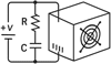 In household electronics or DIY projects, one common problem is residual AC ripple in a DC power supply. By choosing a large capacitor and small resistor, this low-pass filter attenuates unwanted ripple (usually at 50/60 Hz) while letting the DC voltage through. The calculator helps DIY hobbyists select optimal capacitor sizes, avoiding hum in audio devices, flicker in LED lights, or instability in small microcontroller projects.


|