| www.tmatlantic.com
Test & Soldering Equipment On-line Store |
|
D.E.V.I.C.E. (Wiki)Calculators Services |
|||||
Filter by first letter
|
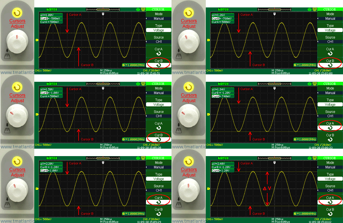
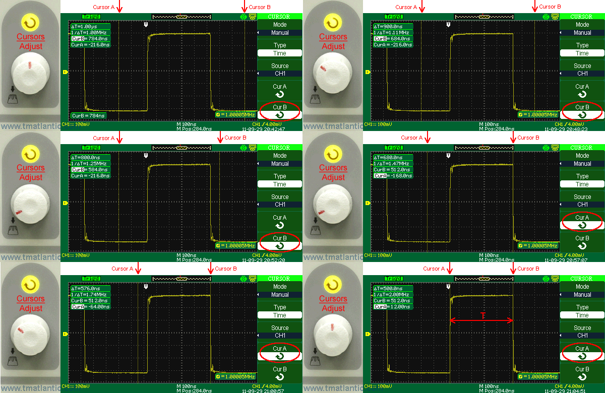
Cursor measurements“Cursor measurements” is the mode in which an oscilloscope determines the cursors positions on Y- or X-axes and calculates the difference between these cursors positions. Y-cursors are displayed as horizontal lines and used for the measurement of vertical parameters. They are usually used for the measurement of amplitude parameters (voltage). X-cursors are displayed as vertical lines and used for the measurement of horizontal parameters. They are usually used for the measurement of time, phase and frequency parameters. Cursor measurements function has three modes: Manual, Track and Auto. Manual modeIn this mode the cursors are displayed as two parallel lines. These cursor lines can be moved along the oscillogram to choose the voltage ranges under measurement:
or time intervals (phase, frequency):
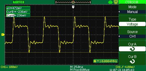
The measured values will be displayed (usually in frames) In the picture below you can see a manual setting of the cursor to measure the signal swing
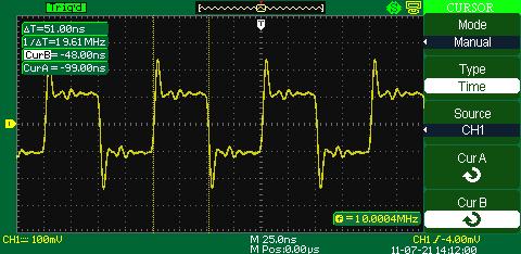
The next picture shows the manual cursor setting to measure positive pulse duration
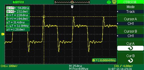
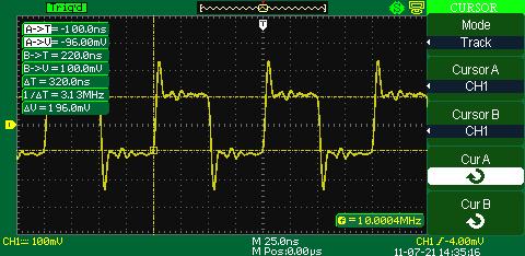
Track modeIn this mode the cursors are displayed in the form of two crossed lines. Cursor crossline fixes its position on the signal line automatically. The cursors can be moved in the horizontal direction along the line of the signal oscillogram by turning of the multifunctional knob.
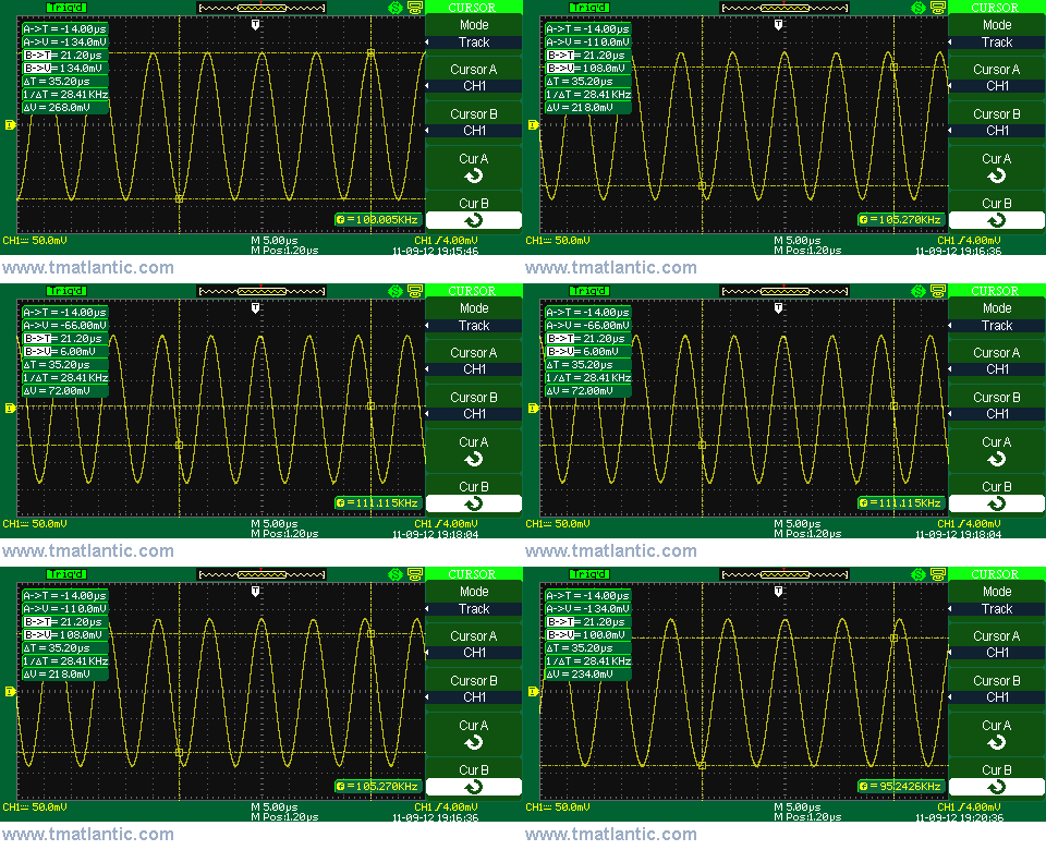
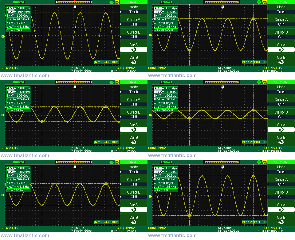
The oscilloscope shows the values of the measured positions in the separate frame on the display. In the picture below you can see automatic measurement of two signal levels in the track mode with the help of horizontal cursors A and B when the vertical cursors are fixed for the changing frequency signal.
The next animated picture shows automatic time measurement in the track mode between the vertical cursors set to measure the signal cycle when its frequency changes.
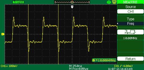
Auto modeThis mode can be seen only when the automatic measurement mode is on. The oscilloscope will automatically display, with the help of cursors, the ways of the measurement of certain parameters. For example: which points the oscilloscope measures frequency at
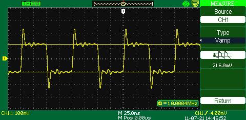
the way it measures the signal voltage range.
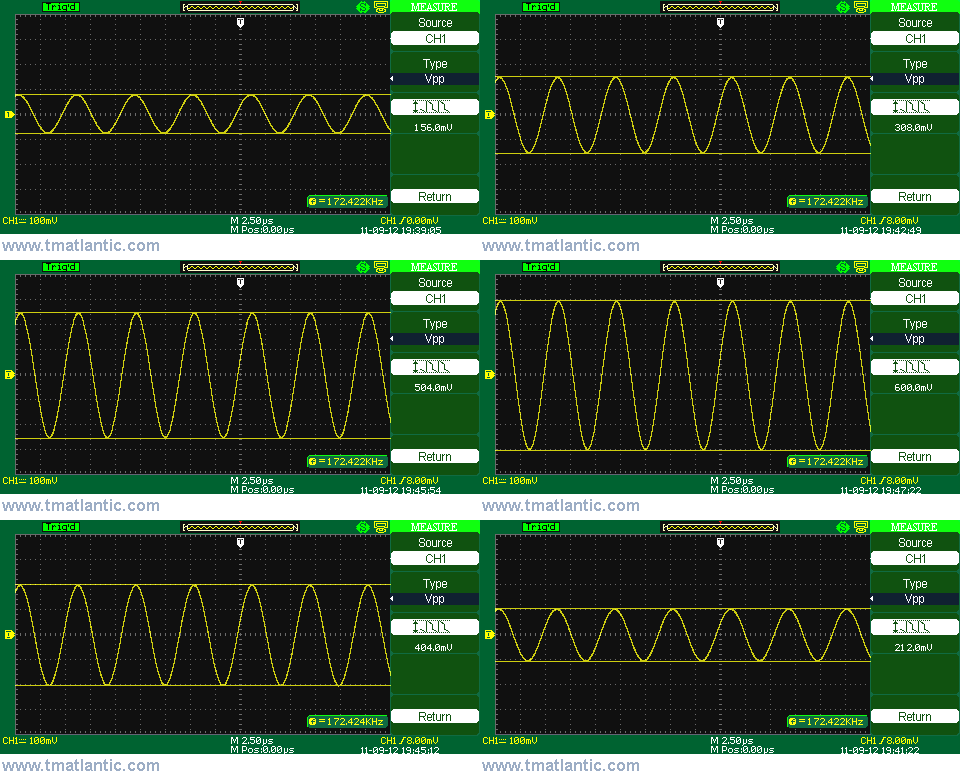
The picture below shows automatic signal swing measurement between the horizontal cursors:
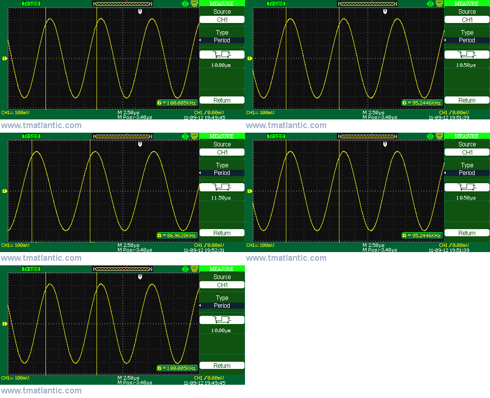
The next picture shows automatic time measurement between the vertical cursors set to measure the signal cycle when its frequency changes
|
Units Converter
|
|
Site mapPrivacy policyTerms of Use & Store PoliciesHow to BuyShippingPayment |


