| www.tmatlantic.com
Test & Soldering Equipment On-line Store |
D.E.V.I.C.E. (Wiki)Calculators Services |
||||||
Filter by first letter
|
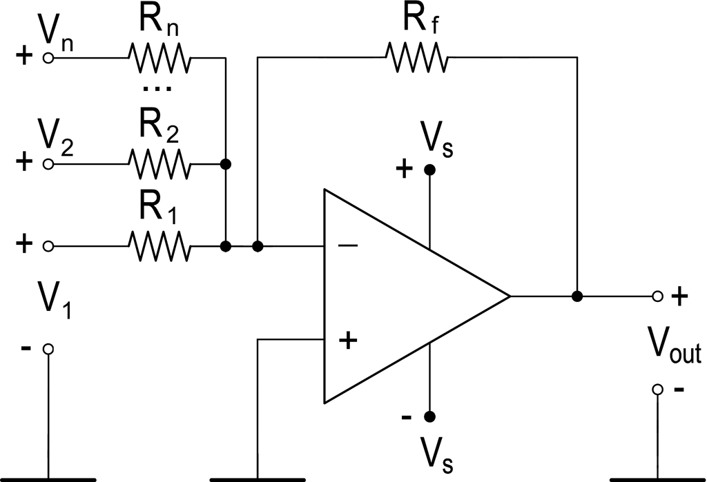
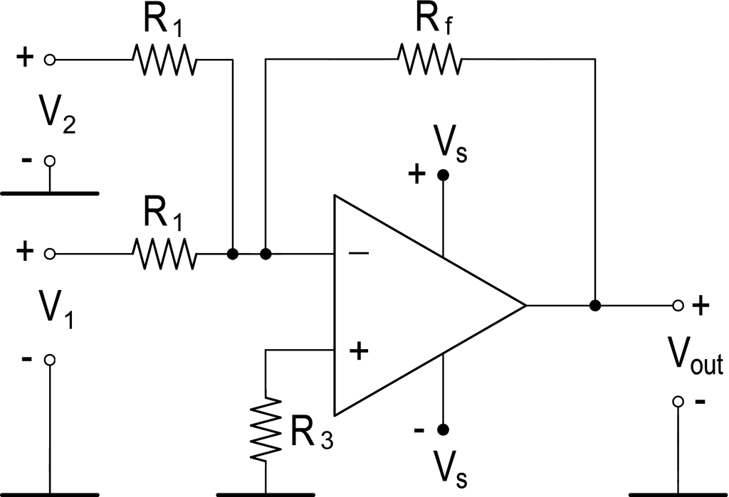
Summing amplifier - inverting amplifier-summerA summing amplifier based on an operational amplifier is most often built on the basis of an inverting amplifier and is shown in Fig. 1 and 2.
At the output of the summing amplifier, the voltage (Vout) is formed, as the sum of the input voltages according to the formulas: 1. In general form: Vout = –Rf × (V1 / R1 + V2 / R2 + … + Vn / Rn) 2. For the case R1=R2=…=Rn, then: Vout = –(Rf / R1) × (V1 + V2 + … + Vn) 3. For the case R1=R2=…=Rn=Rf, then: Vout = –(V1 + V2 + … + Vn) The resistance of resistor R3, connected to the non-inverting input of the op-amp to compensate for the bias current (Fig. 2), is equal to the resistance of the resistor in the feedback circuit, connected in parallel. For the correct operation of the summing element, the signal sources must have the lowest possible output resistance, so that the calculation result is not affected by the low input resistance of the element, and the signal sources do not shunt each other. Use our online Summing Amplifier Calculator. Frequently Asked QuestionsWhat is the concept of a "virtual ground" in a summing amplifier circuit? In an ideal op-amp circuit with negative feedback, the differential input voltage is driven to zero. Because the non-inverting terminal (+) is physically connected to the actual 0 V ground, the op-amp forces the inverting terminal (-) to rest at exactly 0 V as well. This node is called a virtual ground. It is a massive advantage because it mathematically isolates the input channels from one another, preventing changes in one channel's input voltage or resistance from leaking back and interfering with neighboring channels.
How do power supply rails affect the output calculation boundaries? A real-world operational amplifier cannot generate an output voltage higher or lower than its physical power supply rails (+Vs and -Vs). If your inputs sum up to a calculated value of -15 V, but your op-amp is powered by a ±12 V rail, the output will flatten out (clip) abruptly near -11 V or -12 V, causing heavy signal clipping and distortion.
Can I use a summing amplifier circuit to mix alternating current (AC) audio signals? Yes, this is the exact engineering principle behind multi-channel analog studio audio mixers. When mixing AC audio waves, the summing amplifier calculates the instantaneous vector sum of all overlapping audio frequencies in real-time. Because of the virtual ground node, there is zero crosstalk or signal bleed between individual microphones or instrument lines, delivering an incredibly clean audio mix.
|
Measurement History Events
Units Converter
|


|