| www.tmatlantic.com
Test & Soldering Equipment On-line Store |
|
D.E.V.I.C.E. (Wiki)Calculators Services |
|||||
Filter by first letter
|
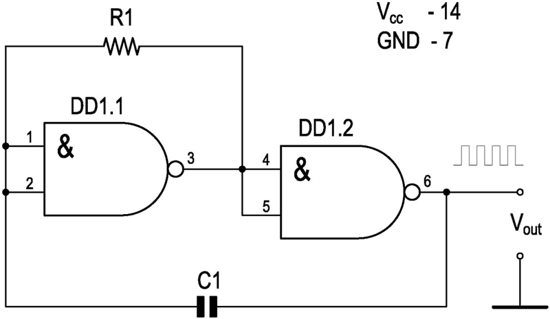
Simple square wave generator using logical elementsA simple square wave generator circuit can be assembled using logical elements. The main advantage of this generator is nothing superfluous: a timing RC chain and two microcircuit elements. The output is a square wave with a frequency that depends on the values of R and C. Duty factor is 50%.
This device can be assembled on any Quadruple 2-Input NAND Gates type chip (For example, HD74LS00P or SN74HC00N or similar). Quadruple 2-Input NAND Gates contains 4 2-Input NAND Gates logic elements. The 2-Input NAND Gates has two inputs, and first applies an AND operation to the two input signals, and then the result is inverted (NOT operation). Logic table:
In the diagram, the inputs of the 2-Input NAND Gates elements are connected to each other. This is done to use only the inversion operation. One 2-Input NAND Gates element inverts the signal, that is, rotates it 180 degrees. Two consecutive elements will rotate the signal 360 degrees = 0 degrees. This is the positive feedback necessary for the generator to operate. Briefly and simplified - operating principleThe input resistance of DD elements is large. After turning on the power, the DD1.1 input became low because capacitor C1 was not charged. This means that the output will have a high level, which goes to the input of DD1.2, the output of which will again be a low level. Through resistor R1, which is connected with the right terminal to output DD1.1 - to the point where the potential of the high capacitor C1 begins to charge. Gradually, the voltage on C1 increases, and at some point a sufficient voltage level will accumulate on the left plate, which will switch DD1.1 to state 1 at the input, 0 at the output. Immediately DD1.2 will change its state to the opposite: 0 at the input, 1 at the output. And the processes in the RC circuit will go in the opposite direction, until the voltage on the capacitor again switches DD1.1, followed by DD1.2, and the whole cycle repeats all over again. Approximate formula for calculating frequency:
f(Hz) = 0.7 / (C1(F) Ч R1(Ω)) The frequency of the generator is determined by the parameters of the timing RC circuit: the resistance of the resistor and the capacitance of the capacitor will determine how long the charge/discharge of the capacitor will last. The frequency of such a generator is unstable. The frequency depends on the supply voltage and temperature. To increase stability, it is recommended to replace the capacitor with a quartz resonator of the desired frequency, and also add one or two more 2-Input NAND Gates elements at the output. |
|
Site mapPrivacy policyTerms of Use & Store PoliciesHow to BuyShippingPayment |


