| www.tmatlantic.com
Test & Soldering Equipment On-line Store |
D.E.V.I.C.E. (Wiki)Calculators Services |
||||||
Filter by first letter
|
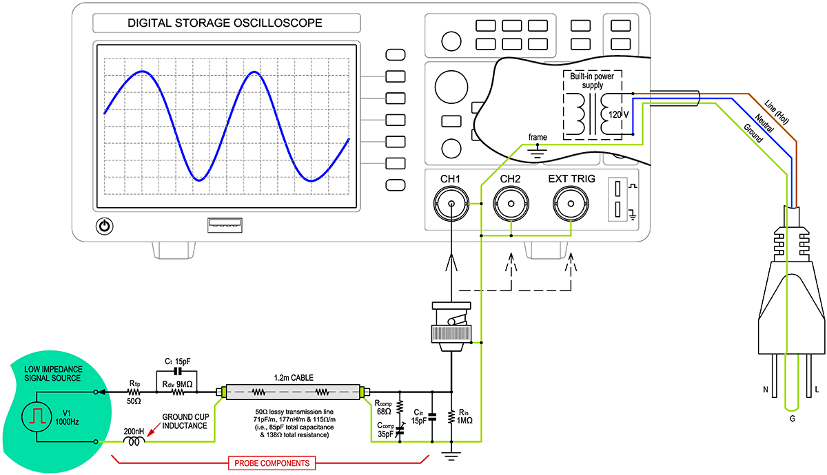
Safely make floating oscilloscope measurements in a variety of challenging environmentsTypical oscilloscope measurements are based on the study of externally powered electronic circuits. Usually the power is supplied from a laboratory power supply, and there is a transformer inside, and thus there is a galvanic isolation from the laboratory / office / home electrical grid. You can use a benchtop oscilloscope with its input probes (example T5060). The structure of the benchtop oscilloscope (example ADS-2121MV) is shown on Figure 1.
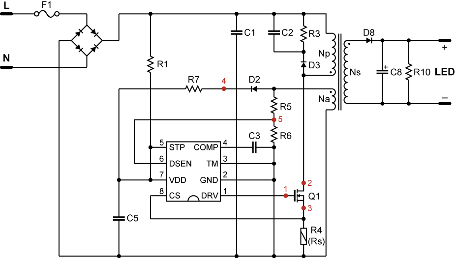
All measurements with a benchtop oscilloscope will be taken relative to ground. Moreover, the "earths" of the laboratory / office / home electrical grid! Such measurements should be properly referred to as "single-ended probe measurements". And all probes of the type - asymmetrical. If the external power supply of the circuit under study does not have galvanic isolation, it is necessary to significantly change the measurement circuit. Why? The whole reason is in the "probe ground" and, accordingly, the "oscilloscope ground". And in Figure 1 you can see that this is the "earth" of the laboratory / office / home electrical grid! For example, you need to measure a simple circuit of a popular LED driver device. LED driver circuit (approximate) is shown on Figure 2.
It shows that the connection to the terminals (points 1, 2, 3) of the transistor Q1 (left side of the circuit) of a benchtop oscilloscope with probes is unacceptable. How to solve this problem? There are several options:
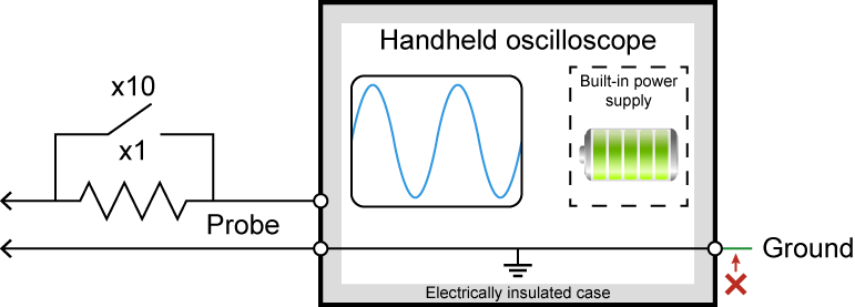
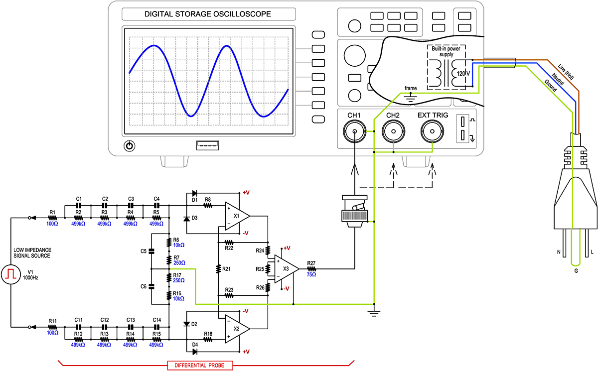
A differential high voltage probe provides "symmetrical measurements". It provides safe measurements in the left (high voltage) side of the LED driver circuit (Figure 5). Not all high-voltage differential probes have built-in isolation, so it is recommended that you use a handheld, battery-powered oscilloscope with the ground disconnected for safe measurements.
|
Measurement History Events
Units Converter
|


|