Logic analyzer

Logic analyzer is a multichannel device for acquisition, saving and displaying of data which represents the order of zero and units (logic state) depending on the input signal, bigger or less the specified threshold level. Logic analyzers can be of the following types:

  • self-contained – a single unit
  • PC-based, they have a separate data acquisition block and operate jointly with a PC through interface (add-on to a PC)

Logic analyzers demonstrate the collected data as follows:

  • Temporary diagram
  • String of codes
  • Decoded codes (in case of a special software availability)

Logic analyzer is capable of operating in synchronous and asynchronous modes:

  • Synchronous mode (state registration) – data acquisition mode when the digitization moment of the logic analyzer input states is defined by the synchronizing pulses coming from the circuit under test to a separate input of logic analyzer
  • Asynchronous mode is data acquisition mode when the digitization moment of the logic analyzer input states is defined by the frequency specified by the internal generator of logic analyzer

Logic analyzers implement various launch and synchronization methods. There is data acquisition launch – the beginning of input data registration; and synchronization launch – the event which connects the registered data with a known point on the time scale. There are following synchronization methods:

  • edge (fall)
  • pattern (a sample of input data combination); order and duration of the pattern (patterns)
  • combination of both synchronization methods (can be specified as well).

Nowadays logic analyzers can be built-in as a block into digital storage oscilloscopes herewith forming a category of mixed signal oscilloscopes.

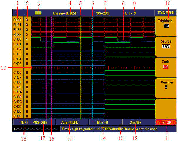
Example of oscilloscope with logic analyzer: AKTAKOM ADS-2182, user interface of logic analyzer:

  1. Channel and Bus indicator: displays current working channel and bus.
  2. Channel binary value display: displays binary system value for the channel position in the current cursor.
  3. Battery powers indicate: indicate battery power when battery inside.
  4. Decimal system value indicate the position of current cursor in storage area.
  5. Yellow dashed line indicates current cursor.
  6. Blue dashed line indicates current trigger position.
  7. Percentage value indicate current trigger position in storage area.
  8. Sample data area indication: red for bus, blue and green for “0”, “1” in each channel data.
  9. Decimal system value indicate the position of current cursor relate to current trigger.
  10. Operation options indicate current function menu and different function menu have different display.
  11. Sample status indicate: “RUN” for sampling and wait for trigger, “TRIG” for trigger detected and wait for sample finished. “STOP” for sampling finished.
  12. Value indicate current time base.
  13. Info windows: different operation display different info.
  14. Value display current filter modulus setting.
  15. Value display current sample rate setting.
  16. Two purple lines for cursor 1 and cursor 2 in cursor measurement.
  17. Percentage value indicate trigger position for next sampling in storage area.
  18. Red square indicate the current sampling data position in storage area.
  19. Red scale line indicates the time base width in sampling data display area and totally 4.8 divisions. The width between two long scale lines is 1 division and between short scale lines are 0.1 divisions.

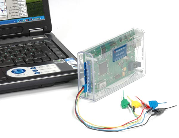
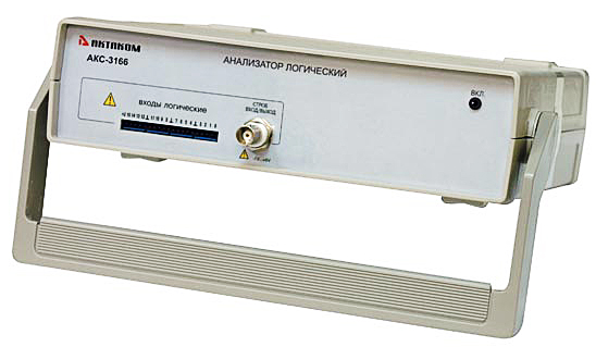
Examples of PC-based logic analyzers: AKTAKOM AKC-3116 and AKC-3166.


Back to the list

Search by section D.E.V.I.C.E. services

Measurement History Events
Yesterday Today Tomorrow
04/07/1795
and annually
Metric System Day

Units Converter

AKTAKOM - the Best in Test Award Winner!
Site map|Privacy policy|Terms of Use & Store Policies|How to Buy|Shipping|Payment|© T&M Atlantic, Inc., 2010-2024