| www.tmatlantic.com
Test & Soldering Equipment On-line Store |
D.E.V.I.C.E. (Wiki)Calculators Services |
||||||
Filter by first letter
|
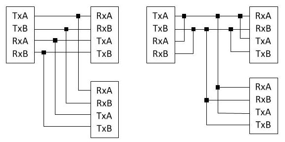
RS-485 (Recommended Standard 485)RS-485 interface features – the ability to switch the transmitters into the third state and the use of differential transceivers with a separate twisted-pair of wires for every signal circuit. On a transmitter outputs signals usually switch between 0 +5V levels. As opposed to RS-232 there is no standard for the pinout in RS-485 interface. One transmitter can work for several receivers. There can be 2 versions of RS-485 interface: two-wire and four-wire.
Four-wire version allocates a master node (master) which sensor works for the receivers of the others. The master transmitter is always active, it doesn’t need to switch into the third state. The transmitters of the other slave nodes (slave) should have tristate outputs, they unit with the master transmitter on the common bus. In the two-wire version all of the nodes have equal rights. Below there is an oscillogram of A and B signals and their remainder (A – B) of the transmitter differential outputs when transferring 16 B with the following symbols: 00h, 11h, 22h,…FFh.
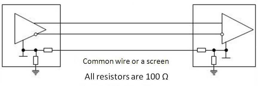
Interface differential input protects from the noise effects but at the same time there should be the connection of “circuit grounds” of the devices with each other as well as with the ground bus. To connect the devices to each other they use the third interface wire (the screen can be also used). To prevent the third wire from high current going through it, smoothing “ground potentials”, there should be resistors included in its circuit.
RS-485 interface is popular as industrial automation device buses. |
Units Converter
|


|