| www.tmatlantic.com
Test & Soldering Equipment On-line Store |
D.E.V.I.C.E. (Wiki)Calculators Services |
||||||
How to use - Oscilloscope Current ProbeOscilloscope current probe is a measuring head for oscilloscopes used to explore circuit current forms without breaking the network integrity under research. Current probes allows exploring both AC (in the given frequency band) and DC circuits.
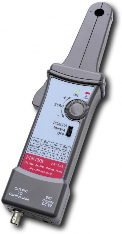
Fig.1. Example of a modern current probe Often user would like to explore not voltage but current with the help of an oscilloscope. Therefore you may use a low-resistance shunt in the circuit break and convert current to voltage in accordance with the following formula: U=RI. For example, if the oscilloscope sensitivity is 5 mV/div that means when the shunt resistance is 1 Ohm (R = 1 Ohm) we get the current sensitivity of 5 mA/div. But this method has several disadvantages:
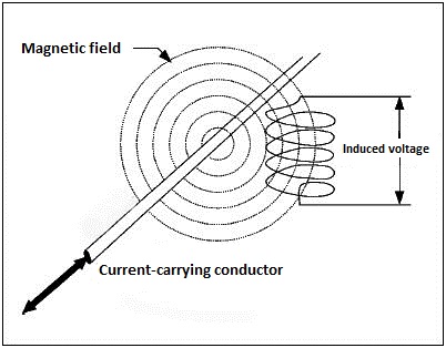
Due to these reasons it is recommended to use non-contact current probes which operation is based on the recording of magnetic field that appears around the conductor by passing current I through it. To increase the sensitivity the probe head is made in form of a current transformer which operation principle is well-known, or basing on Hall sensor use.
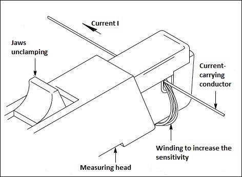
Fig.2. Current control principle in the conductor by its magnetic field When unclamping the jaws of the clamp meter you open the magnetic conductor and after that you can insert the wire, where the current is measured and observed, into the gap. To increase the sensitivity and measure low currents you may create a wire winding with several coils that will increase the magnetic flux in the sensor.
Fig.3. Wire winding with several coils To measure the summed and differential current it’s possible to insert the measuring head of the current probe of two conductors into the gap. Typically when using a special current calibrator current measurement error after the probe calibration can be ± 1% (or better) for currents from 0.05 to 5 A and ± 2% for currents from 5 to 15 A. |

|