| www.tmatlantic.com
Test & Soldering Equipment On-line Store |
|
D.E.V.I.C.E. (Wiki)Calculators Services |
|||||



How to Convert an LED Light Fixture from a Series Circuit to a Parallel CircuitContents
Improve Reliability and Extend the Life of Your LED FixtureMany low-cost LED light fixtures use a series-connected LED circuit powered by a constant-current driver. While this design is inexpensive to manufacture, it has one significant drawback: the failure of a single LED can cause the entire fixture to stop working. In this article, we'll explain why this happens and demonstrate how converting the fixture to a parallel LED circuit with a constant-voltage driver dramatically improves reliability. Step 1: Understand the Original Circuit
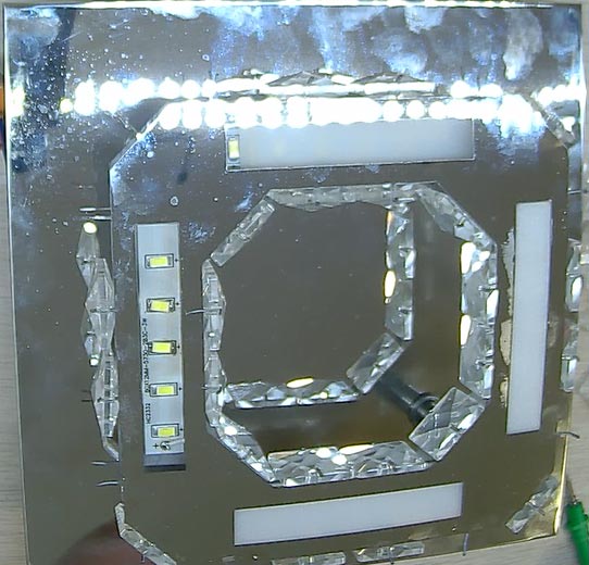
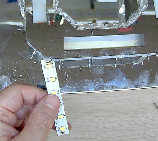
Begin by opening the LED light fixture and removing the diffuser to expose the LED strips (Pic. 1). In the original design, the fixture consists of:
Because every strip is connected in series, the same current flows through every LED in the fixture. Although this design is simple, it creates a single point of failure. Step 2: Identify the Weakness of the Series Circuit
Suppose one LED overheats due to poor thermal management, manufacturing defects, or normal aging. When one LED in a series-connected pair fails, the remaining LED in that pair is subjected to much greater electrical and thermal stress. The overloaded LED quickly fails as well. Once the circuit is opened, the constant-current driver can no longer maintain current through the series chain, and the entire light fixture turns off. A single defective LED can therefore disable the entire fixture.
Step 3: Remove the Original LED Circuit
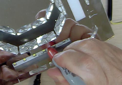
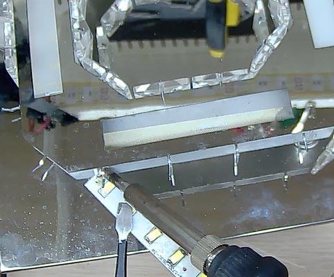
Disconnect the constant-current driver. Carefully remove the existing LED strips from the aluminum housing (see Pic. 4). Inspect the heat sink surface and remove any old thermal compound or adhesive. Clean the mounting surface before installing the new LED strips. Step 4: Prepare the New Parallel LED Circuit
The upgraded design uses:
Unlike the original fixture, every LED strip will operate independently. If one strip develops a fault, the remaining strips continue operating normally.
Step 5: Install the LED Strips
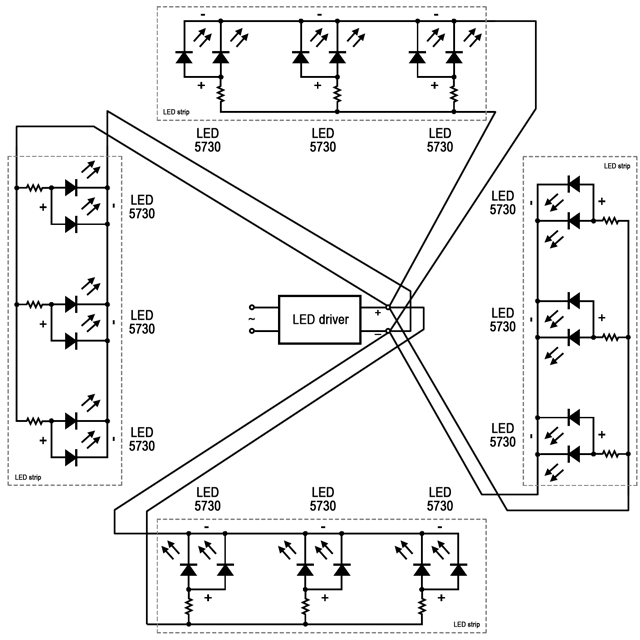
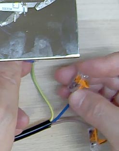
Mount each LED strip securely onto the aluminum housing. Ensure there is good thermal contact between the LED boards and the heat sink. Proper cooling significantly extends LED life and improves long-term reliability. Step 6: Connect the LED Strips in ParallelConnect every LED strip directly to the constant-voltage driver. Each strip should have:
All four strips are connected in parallel across the driver output. Within each strip, every LED branch includes its own current-limiting resistor to regulate current independently. This arrangement prevents one failed LED from affecting the rest of the fixture. Step 7: Inspect the Wiring
Before applying power:
A careful inspection helps prevent damage during initial power-up. Step 8: Reassemble the Fixture
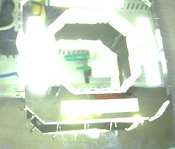
Once testing is complete, reinstall the diffuser and reassemble the light fixture. Restore power and verify that all LED strips illuminate evenly. If everything has been wired correctly, the fixture should produce uniform brightness across all strips. Step 9: Verify the Improved DesignThe upgraded fixture now operates using a completely different electrical architecture. Instead of one long series circuit, each LED strip functions independently. If one LED branch eventually fails:
This eliminates the most common cause of complete LED fixture failure. Advantages of the Parallel LED DesignCompared with the original series-connected circuit, the upgraded design offers several important benefits:
ConclusionConverting an LED light fixture from a series-connected circuit to a parallel circuit is one of the most effective ways to improve reliability. By replacing the constant-current driver with a constant-voltage driver and wiring each LED strip independently, the fixture becomes far more tolerant of individual LED failures. Instead of one defective LED shutting down the entire light, only the affected branch is impacted while the rest of the fixture continues operating normally. A well-designed parallel LED circuit, combined with proper thermal management and quality components, can provide many years of dependable, trouble-free service. This simple engineering improvement transforms an inexpensive LED fixture into a more reliable and maintainable lighting system. Improving LED Fixture Reliability – Video TutorialFrequently Asked QuestionsWhen Is It Reasonable to Repair an LED Light Fixture?Repairing an LED light fixture is often the most cost-effective option when the problem is limited to a few failed components rather than the entire fixture. A repair is usually worthwhile if:
In many cases, upgrading the internal LED strips or converting them to a more reliable configuration (such as parallel-connected LED strips) can significantly extend the fixture's lifespan and improve reliability. However, replacement may be the better choice if the fixture has extensive heat damage, corrosion, water damage, or replacement parts are no longer available.
What Is the Average Cost of LED Light Fixture Repair?The cost of repairing an LED light fixture depends on the type of failure and the complexity of the repair. Typical repair costs are:
For high-end architectural, commercial, or specialty fixtures, repairing the existing unit is often much less expensive than replacing it, especially when a new fixture costs several hundred dollars or more. A professional diagnosis can determine whether a repair is practical and provide an estimate before any work begins. IMPORTANT SAFETY NOTICE & DISCLAIMER WARNING
ELECTRICAL
HAZARD The information provided on this website is for educational and general diagnostic purposes only. WARNING: Performing electrical work carries inherent risks of severe injury, electrocution, or property damage. Before inspecting or troubleshooting any electrical appliance, you must read the manufacturer's instruction manual (specifically the troubleshooting section) and completely disconnect the device from the power source by unplugging it from the electrical outlet. Simply turning the device off using its power switch is NOT sufficient to eliminate electrical hazards. Under Florida law (Chapter 489, Florida Statutes), property owners are generally permitted to perform basic inspection and diagnostic tasks on their own property. However, electrical installations, alterations, or complex repairs must be performed exclusively by a licensed and certified electrical contractor. Do not attempt complex repairs yourself. |



|