Aktakom Power Manager Max Pro software allows users to remotely control their AKTAKOM power supply via PC. It features Measure, Set Up and Initialization functions, as well as, automatic switching off of the outputs of the device at the end of the program. The program follows basic configurations and some features of operation as the device control panel.
Software Specification
|
Connection, communication
|
USB, LAN
|
|
Load voltage indication
|
Yes
|
|
Load current indication
|
Yes
|
|
Load power indication
|
Yes
|
|
Indication of operation under load
|
Yes
|
|
Operating mode indication
|
V C / C C
|
|
Digital input of voltage and current values
|
Yes
|
|
Regulator for entering voltage and current values
|
Horizontal - Sliding
|
|
Output on/off button
|
Yes
|
|
Preset fixed voltage values
|
Yes
|
|
Preset fixed current values
|
Yes
|
|
Voice guide
|
Yes (On / Off), Eng
|
|
Activate remote control mode
|
Any first command sent from a PC to a power supply using USB or LAN
|
|
Switch to manual control mode
|
"Res" command sent from a software or turn the power supply off and on
|
|
Displaying the history of load voltage and current values
|
Yes
|
|
Work according to a given schedule of current and voltage values
|
Yes
|
|
Saving and importing current and voltage schedules
|
Yes
|
|
Current time clock
|
On / Off
|
|
Button names
|
On / Off
|
|
Help
|
Yes
|
|
Language support
|
EN, ES
|
|
News
|
On / Off
|
Note: Any first command sent from a PC to a power supply using USB or LAN switches power supply to remote control mode. To switch power supply back to manual control mode please use a software to send "Res" command or turn the power supply off and on.
The software is multifunctional and interactive, its pre-set function allows for faster set up and flawless changes. Besides functionality the software has "News" button shows or hides Aktakom news feed. "Info" button displays the information about the program and connected device, and of cause the "Help" button for those who are stuck and need a little help.
Standard package
The software in the standard package of the device has no physical media (CD) and can be downloaded at www.tmatlantic.com after the purchasing and registering the equipment with a serial number. This software is not free however its cost is included into device value.
Control via PC using Aktakom Power Manager Max Pro
Operating procedure
After starting the application, its main window will open:
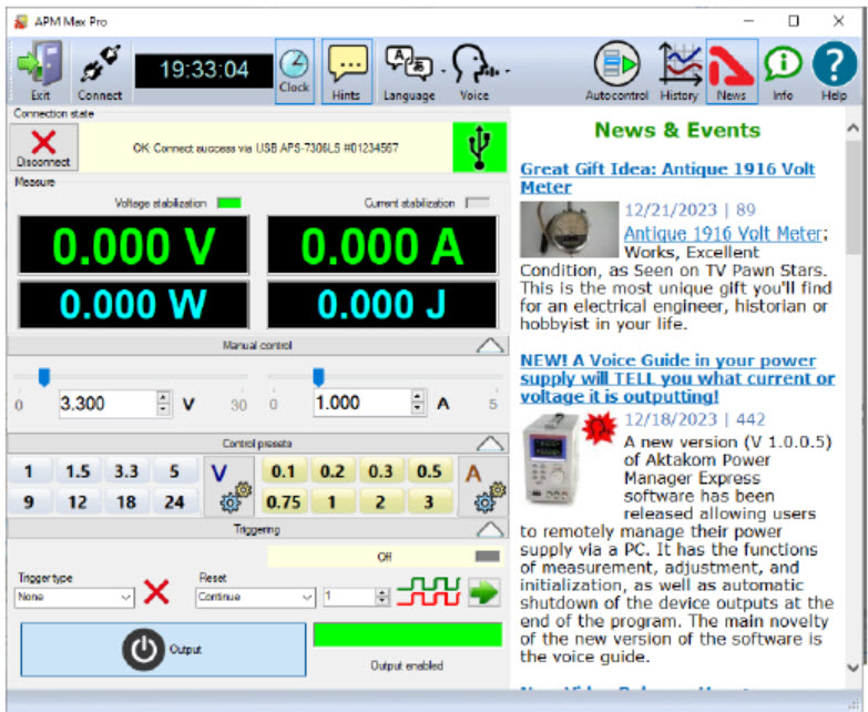
Figure 1.
Upper panel buttons of the main window:
"Exit" button terminates the program operation.
"Connect" button opens device connection dialogue.
The button with a clock icon shows or hides the clock display on the keypad.
"Hints" button shows or hides the keys caption text.
Button "Turn OFF when closed" - enables/disables the mode of automatic switching off of the outputs of the device at the end of the program.
"Voice" - Selects a Windows voice guide that will announce application events to you.
Select the "No voice" option to disable the voice guide.
"Autocontrol" - Recalls the automatic control panel using a specified list of commands.
"History" - Opens the application event history window.
"News" button shows or hides Aktakom news feed.
"Info" button displays the information about the program and connected device.
"Help" button recalls this help file.
Device Connect
When the application is running the power supply connection window will open:
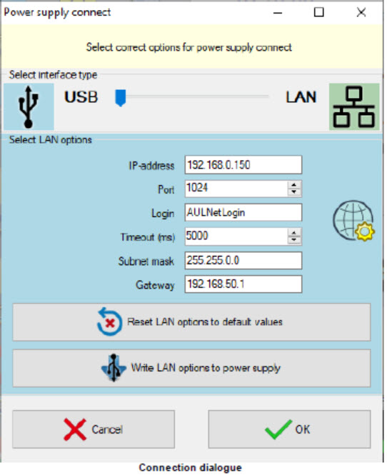
Figure 2.
Select the necessary interface type (USB or LAN), enter the settings for the network connection (IP address (IPv4), Subnet mask, Gateway) and press OK button to connect to the power supply. If the program successfully detects the device and reads its serial number, it will ask you for a license key to work with it. Find the string of the key that you received when purchasing the program or device, enter it in the dialog and click OK:
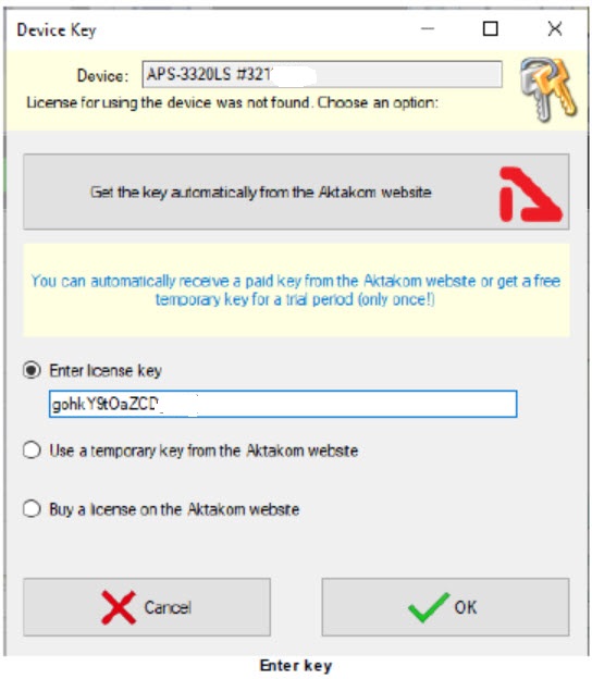
Figure 3.
You will see the connection state in the main program window, "Connection state" block.
In case of successful connection the program will remember the settings and next time it will try to use them to reconnect to the device.
To restore the connection break in the program operation click "Connect" button in the main window. Also use this window to record the network settings to the power supply memory. To do this open "Connection" window after the device connection via USB, enter the necessary settings in IP, port, login fields and click "Write LAN options to power supply." When recording you will need to enter a password (default password: AULNetPass).
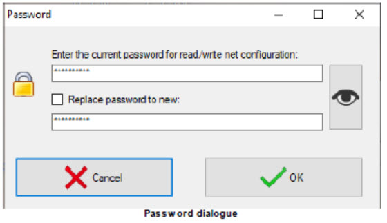
Figure 4.
To change the password check box "Replace password to new".
If the USB interface is used and more than one power supply is connected to the computer, a dialog for selecting the desired device from the list will appear (Fig. 5).
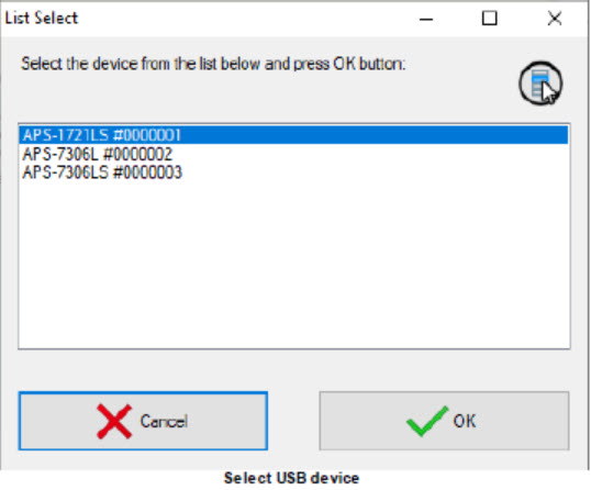
Figure 5.
Manual Control
After the device connection its current state will be displayed in Measurements block.
Constant voltage and current mode is controlled by the elements of Control block. To switch on/off the output use Exit key.
Synchronization block allows you to use the synchronization input capabilities for the device models equipped with it.
Trigger type:
- No. Synchronization is not used.
- Rise. The device outputs switch their state when there is a transition detected from the lower state of the synchronization line to the upper one.
- Fall. The device outputs switch their state when there is a transition detected from the upper state of the synchronization line to the lower one.
- Any. The device outputs switch their state when there is any transition detected on the synchronization line – from the lower state to the upper one and vice versa.
- Set. The device outputs turn on if the synchronization line is in the upper state and turn off if the synchronization line is in the lower state.
- Inversion. The device outputs turn off if the synchronization line is in the upper state, and turn on if the synchronization line is in the lower state.
Restart:
- Continue. Multiple mode. After processing the detected synchronization event the startup system returns to the start waiting state.
- Single mode. After processing the detected synchronization event the startup system stops operating. To switch it to the start waiting state press the restart key.
Counter:
- It is used in multiple mode ("Continue"). If set to zero the synchronization is restarted an unlimited number of times. If set to the number greater than zero the synchronization is restarted the specified number of times and thereafter it turns off as in a single mode.
Synchronization state indicator:
- Grey color. The synchronization system is off.
- Yellow color. The synchronization system is in the start waiting state
- Green color. The synchronization system has detected a start event and sent a start
command.
- Red color. The synchronization system is stopped and requires the user's command to process the next start event.
Note:
Disable/Enable outputs button has priority over the synchronization settings. When the output is allowed (the key is pressed), the synchronization will control the outputs state, but if it is disabled (the key is released, off), the outputs will be always disabled regardless of the synchronization state.
Presets list edit
The appearance of the dialog box in the picture below.
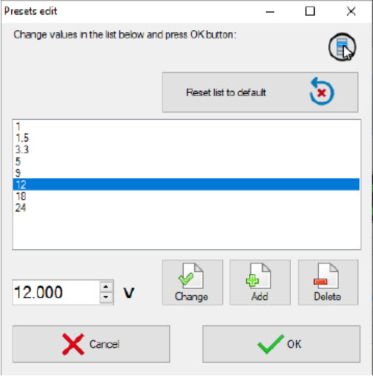
Figure 6.
The list of presets (shortcut buttons) is a list of Voltage or Current values, which can be set on the device "with one touch". In dialogue editing presets in addition to the list itself, the program displays the following buttons:
Reset list to default - return the contents of the list to default values.
Change - replace the selected line of the list with the entered value.
Add - add a new value to the list.
Delete - remove the current line from the list.
Cancel - close the dialog without saving changes.
OK - save changes and close the dialog.
Autocontrol
The appearance of the window in the picture below.
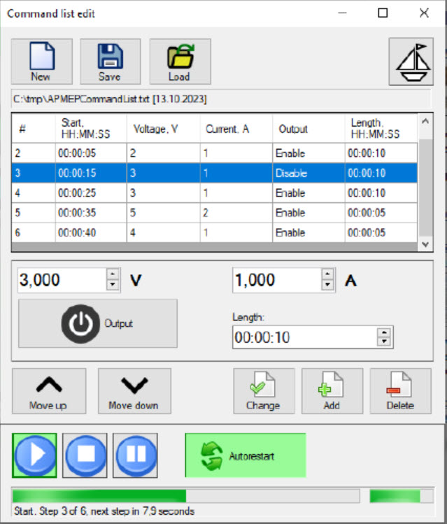
Figure 7.
The panel makes allows the user to specify a list of commands that will be automatically sent to the device sequentially.
The sequence consists of steps that include: voltage and current values, output status, and step duration.
Click the New button to create a new list of commands. Set the necessary parameters for the first step, and add it to the list using the Add button. Add all subsequent steps in the same way. If necessary, correct the order of steps using the Move Up and Move
Down buttons. To change the values of a step, select it in the list of commands, set the desired values and click the Change button. To remove an unnecessary step, select it and click the Delete button.
Save the list of commands to a file using the Save button. In the future, you can load itagain using the Load button.
To control the execution of the list, use the buttons at the bottom of the panel: Start, Stop, Pause. To repeat the list execution cyclically, click the Autorestart button. The progress will be displayed at the bottom of the block.
Please note that in auto-control mode, the Set Up block of the main program window will change its background color to light green. In this case, the controls of the main window are not blocked; if necessary, you can quickly manually control the device without interrupting the sequence of automatic commands.
The button with a boat in the upper right corner of the window turns the "floating" panel mode on and off. In floating mode, a window remains on top of other windows even if it is no longer active.
History
The appearance of the panel in the picture below.
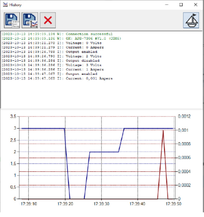
Figure 8.
The application event history window consists of two main parts.
The upper part is a text protocol, the lower part is a graph of voltage and current values measured at the output of the device. The left scale of the graph is voltage, the right is current.
Top buttons from left to right:
- save the text protocol to a file;
- save chart data to a file;
- clear the history.
The button with a boat in the upper right corner of the window turns the "floating" panel mode on and off. In floating mode, a window remains on top of other windows even if it is no longer active.