|
Course: EE-31 Embedded Systems for Smart Home (ESP32, Sensors, Firmware)
Course: EE-31 Embedded Systems for Smart Home (ESP32, Sensors, Firmware)

Click an image to enlarge
|
|
|
This course provides a hands-on introduction to embedded systems design for smart home applications, centered around the ESP32. Students will learn how to interface sensors and actuators, develop firmware, and build reliable, low-power IoT devices. Topics include microcontroller architecture, GPIO and communication protocols (I²C, SPI, UART), real-time data processing, and wireless connectivity such as Wi-Fi and Bluetooth. The course emphasizes practical projects, enabling students to design, program, and deploy fully functional smart home solutions.
Objective and audience
This course teaches participants how to design, program, and build low-voltage smart home nodes based on the ESP32 microcontroller, interface digital/analog sensors, and write stable custom firmware with secure Wi-Fi/MQTT communications.
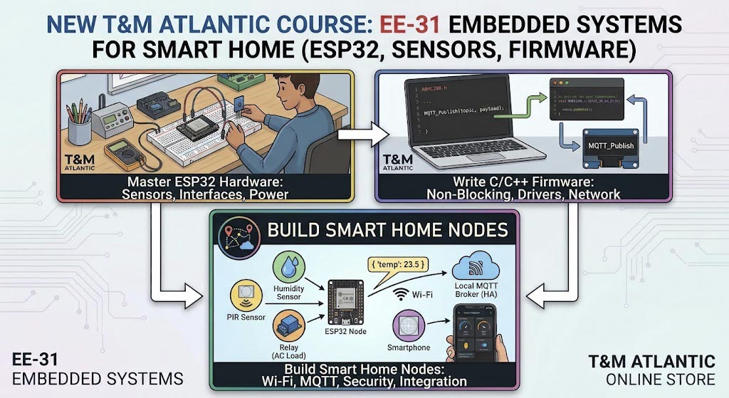
The course is intended for students, maker-space enthusiasts, entry-level firmware developers, and automation technicians who already understand basic circuit concepts (voltage, current, digital/analog signals) and elementary programming fundamentals (C/C++ loops and logic). Familiarity with basic electrical measurement tools is helpful; courses EE-3 Basics of Electronics and EE-6 Basics of measuring with a multimeter provide useful preparation.
Proposed format
Ten 90-minute lessons, totaling 15 instructional hours. Approximately one-third of each lesson consists of technical explanation and live demonstration; the remainder is hands-on firmware writing, circuit breadboarding, measurement, and debugging. Instructor-led lab sessions or remote interactive sessions are supported if participants have the required hardware kit. Exercises utilize low-voltage, breadboard-friendly ESP32 development boards and standardized sensor modules with accessible GPIO pins.
Learning outcomes
By the end of the course, participants will be able to:
- Safely power and interface an ESP32 micro-controller board with external sensors and actuators.
- Read and process both analog and digital sensor signals (GPIO, ADC, I²C, SPI, UART).
- Program modular, non-blocking firmware in C/C++ using platform libraries (ESP-IDF or Arduino core).
- Establish secure Wi-Fi connections and implement MQTT protocol communication with local smart home brokers (e.g., Home Assistant or Mosquito).
- Manage power consumption and use sleep modes (Light/Deep Sleep) for battery-driven nodes.
- Isolate hardware wiring faults, pin configuration mistakes, and software logic bugs using a multimeter, serial log monitor, and basic signal tools.
Lesson plan
- ESP32 Architecture and Pinout Basics:
Inspect the ESP32 dev kit, pinouts, power rails (3.3V/5V), and strapping pins; set up the IDE/toolchain and write/flash a serial "Hello World" and status LED control program.
- Digital Inputs/Outputs and Interrupts:
Connect physical pushbuttons, motion sensors (PIR), and relays; implement software debouncing and write interrupt service routines (ISR) for immediate hardware events.
- Analog Sensors and ADC Calibration:
Interface analog sensors (photoresistors, thermistors, or soil moisture sensors); read ADC values, calibrate scaling limits, and apply basic digital filtering to smooth noisy readings.
- Bus Protocols I: I²C Sensors and Displays: Understand I²C bus wiring, pull-up resistors, and device addresses; connect and read temperature/humidity sensors (DHT22/BME280) and display live data on an OLED screen.
- Bus Protocols II: SPI and Serial (UART) Peripherals:
Configure SPI and UART interfaces; communicate with high-speed modules (e.g., RFID readers, SD card modules, or GPS modules) and process raw serial data packets.
- PWM, Timers, and Actuator Control:
Generate PWM signals using LEDC channels; control LED brightness, drive servo motors, and safely switch AC/DC loads using optocoupled relay modules.
- Wi-Fi Connectivity and Web Interface:
Configure ESP32 Wi-Fi station and access point modes; manage network reconnection strategies and build a local HTTP web server to monitor sensors and toggle outputs from a browser.
- MQTT Messaging and Smart Home Integration:
Implement MQTT protocol using JSON payloads; connect the ESP32 node to a local broker, publish telemetry data, and subscribe to control topics for automated smart home actions.
- Power Management and Deep Sleep:
Measure power consumption in active and sleep modes; configure Deep Sleep, wake-up triggers (timer and external GPIO), and non-volatile storage (NVS) for preserving node state.
- Troubleshooting and Final Project:
Diagnose instructor-inserted hardware and firmware faults on a multi-sensor smart home node; debug communication timeouts and pin conflicts, then present a fully functional integrated smart home peripheral.
Equipment for exercises
- An ESP32 development board (NodeMCU-32S, ESP32-WROOM, or similar) with USB cable.
- A solderless breadboard, jumper wires, resistors, LEDs, pushbuttons, and optocoupled relay modules.
- A sensor assortment: BME280/DHT22 (I²C/Digital temp & humidity), PIR motion sensor, photoresistor/LDR, and an OLED display (I2C SSD1306).
- A digital multimeter for verifying supply voltages, continuity, and GPIO logic levels.
- A current-limited low-voltage bench supply (5V/3.3V) or USB power monitor.
- A computer with installed IDE (VS Code with PlatformIO or Arduino IDE) and serial terminal monitor.
Safety and scope
- All practical lab exercises operate strictly on safe, low-voltage DC (3.3V to 5V).
- Direct connection of ESP32 GPIOs to 120V/230V AC mains power, unisolated high-voltage circuits, or high-power industrial loads is strictly outside the scope of this course's hands-on exercises.
- When controlling high-voltage appliances in real-world smart home scenarios, participants must use commercially certified isolated relays, smart plugs, or optoisolated driver boards. Never connect microcontrollers directly to mains lines without proper isolation and enclosure standards.
Final assessment
The final exercise is complete when the participant:
- Assembles a multi-sensor ESP32 circuit on a breadboard without electrical shorts or pin contention.
- Writes and flashes modular firmware that reads sensor data at designated intervals and handles Wi-Fi reconnections gracefully.
- Successfully publishes sensor data via MQTT to a test broker and receives remote control commands.
- Demonstrates systematic troubleshooting by resolving a simulated wiring or code error and documenting the diagnosis step by step.
Completion documents performance on the course exercises; this proposal does not claim a formal certification or professional qualification.
Sources and technical references
Back to the section
|
|
|






