The T5060 is a passive, high impedance oscilloscope probe, designed for accurately measuring and displaying electrical signals on an oscilloscope.
What is the T5060 oscilloscope probe used for?
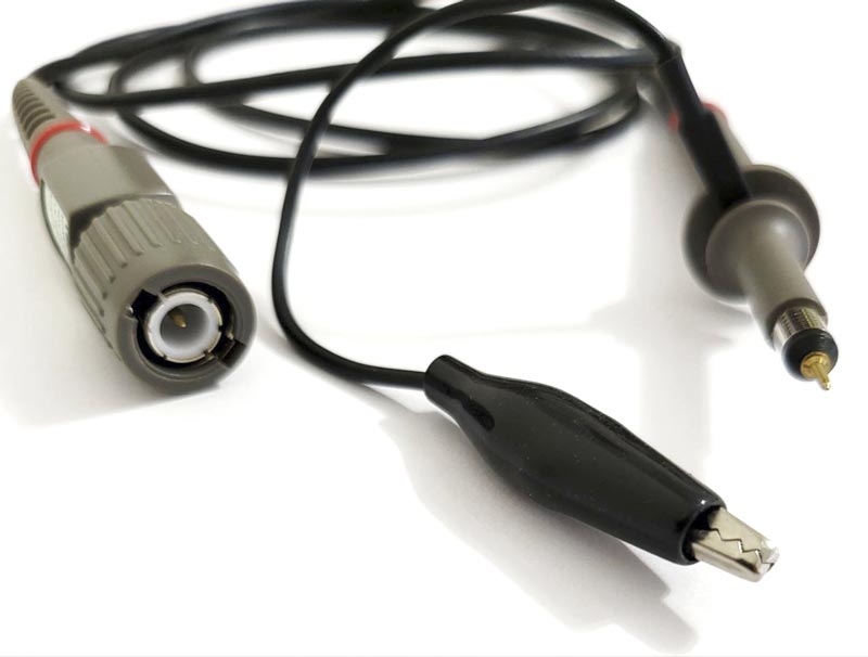
The T5060 probe serves to connect the electrical circuit under test to the oscilloscope input. It performs several key functions:
- Signal Transmission: Physically connects the test point to the oscilloscope.
- Attenuation: It has a switchable attenuation of ×1 and ×10, which allows measuring signals of different amplitudes. The ×10 mode allows measuring higher voltages.
- Isolation and Matching: The high input impedance of the probe (1 MΩ in ×1 mode and 10 MΩ in ×10 mode) minimizes the load on the measured circuit, ensuring more accurate readings.
- Compensation: Allows the probe to be adjusted to the input capacitance of the oscilloscope, ensuring correct display of high-frequency signals, such as square waves.
Which instruments is it used with?
The T5060 probe is designed and calibrated for use with instruments having an input impedance of 1 MΩ. It may be compensated for use with instruments having an input capacitance of 10 pF to 35 pF.
Practical Application Examples
The T5060 probe is ideal for a wide range of electronics tasks:
- Debugging and Analysis of Digital Circuits: Measuring the shape and time parameters of signals in digital circuits (e.g., clock signals, data buses).
- Working with Analog Circuits: Observing and analyzing sinusoidal, sawtooth, and other signals in amplifiers, filters, and oscillators.
- Power Measurement: Analyzing ripple and noise on power lines, including switch-mode power supplies.
- Educational Purposes: Used in educational labs for learning the fundamentals of electronics and oscilloscope operation.
Safety
- Review the safety precautions to avoid injury and prevent damage to the product. Use this product only as specified.
- The common terminal is at ground potential. Do not connect the common terminal to elevated voltages.
- Do not operate in an explosive atmosphere.
Compensation Adjustment
Compensation adjustment is required whenever the probe is transferred from one oscilloscope or input channel to another.
Connect the probe to the oscilloscope and select the ×10 position on the probe switch. Apply a 1 kHz square wave to the probe tip, or connect to the cal socket on the oscilloscope to display a few cycles of the waveform. Adjust the trimmer located in the BNC box for a flat topped square wave. Learn more about probe compensation.