AKTAKOM Power Manager 21 Professional software is designed to remotely control compatible AKTAKOM APS-XXXX power supplies with USB or LAN interface.
Software Specification
|
Connection, communication
|
USB, LAN
|
|
Load voltage indication
|
Yes
|
|
Load current indication
|
Yes
|
|
Load power indication
|
No
|
|
Indication of operation under load
|
Yes
|
|
Operating mode indication
|
CV / CC
|
|
Digital input of voltage and current values
|
Yes
|
|
Regulator for entering voltage and current values
|
Horizontal - Sliding
|
|
Output on/off button
|
Yes
|
|
Preset fixed voltage values
|
Yes
|
|
Preset fixed current values
|
Yes
|
|
Voice guide
|
No
|
|
Activate remote control mode
|
Any first command sent from a PC to a power supply using USB or LAN
|
|
Switch to manual control mode
|
"Res" command sent from a software or turn the power supply off and on
|
|
Displaying the history of load voltage and current values
|
Yes
|
|
Work according to a given schedule of current and voltage values
|
Yes
|
|
Saving and importing current and voltage schedules
|
Yes
|
|
Current time clock
|
On / Off
|
|
Button names
|
On / Off
|
|
Help
|
Yes
|
|
Language support
|
EN, ES
|
|
News
|
On / Off
|
Program description
User interface
Buttons on the top bar of the main window:
The "Exit" button exits the program.
The "Connection" button calls up the dialog for connecting to a power source.
The "Save" button allows you to save the data displayed on the chart to a file.
A button with a clock icon shows or hides the display of the clock on the keypad.
The "Protocol" button opens the program operation history window.
The Tips button shows or hides the display of button labels.
The "Language" menu is used to select the language of the program interface.
The Graph button shows or hides the measurement graph.
The "News" button shows or hides the Aktakom news feed.
The "About" button displays a dialog with information about the program and the connected device.
The "Help" button calls this help file.
Block "Connection status". Shows the current status of connection to the power supply.
Block "Measurements". Contains indicators with the results of measurements of current parameters at the output of the device.
Block "Manual control". Allows manual control of the main current parameters.
Block "Control Templates". Allows you to control current parameters using predefined presets.
Synchronization block. Used to work with the synchronization system (only for models with index S).
Block "Control list". Allows you to control the current parameters automatically using a predefined list of commands.
Note: control and synchronization blocks can be hidden or shown at the user's choice.
The "Output" button turns the current output of the power supply on or off.
Connecting to the device
When you first start the application, the power supply connection dialog will immediately open:
Select the desired interface type (USB or LAN), enter the settings for the network connection (IP address (IPv4), Subnet mask, Gateway) and press the OK button to connect to the power supply.
If the program successfully detects the device and reads its serial number, it will ask you for a license key to work with it. Find the key combination that you received when you purchased the program or device, enter it in the dialog and click OK:
You will see the connection result in the main program window, in the "Connection status" block.
If the connection is successful, the program will remember the settings and the next time you start it, it will try to use them to automatically reconnect to the device. To reset the saved connection settings and return to the factory settings, click the "Reset LAN Settings" button.
To restore the connection after a break while the program is running, click the "Connect" button in the main window. Also use this dialog to write the network settings to the power supply memory. To do this, after connecting to the device via USB, open the "Connection" dialog, enter the necessary settings in the IP, port, login fields and click the "Write LAN settings to power source" button. When recording, you will be asked to enter a password (default password: AULNetPass). The view of the password entry dialog is shown in the figure:
To change the password, check the box "Change password with a new one" and enter a new password in the field below.
If the USB interface is used and more than one power source is connected to the computer, a dialog will appear for selecting the required device from the list:
Manual control
After connecting to the device, its current state will be displayed in the Measurements section of the main program window.
The stabilization voltage and current are controlled by the elements of the Control block. Turning the output on and off is done with the Exit button.
The Synchronization block allows you to use the capabilities of the synchronization input for instrument models equipped with it.
Launch type:
- Not. Synchronization is not used.
- Front. The outputs of the device switch their state when a transition is detected from the lower state of the synchronization line to the upper one.
- Recession. The outputs of the device switch their state when a transition is detected from the upper state of the synchronization line to the lower one.
- Any. The outputs of the device switch their state when any transition is detected on the synchronization line - from low to high or from high to low.
- Installation. The instrument outputs turn on if the sync line is in the up state and turn off if the sync line is in the down state.
- Inversion. The instrument outputs turn off if the sync line is in the up state, and turn on if the sync line is in the down state.
Restart:
- Repeat. After processing the detected synchronization event, the trigger system returns to the pending trigger state.
- One time. After processing the detected synchronization event, the launch system stops. To put it into a state of waiting for the launch, you need to press the restart button.
Counter:
- Used in multiple mode ("Repeat"). If set to zero, the synchronization is restarted an unlimited number of times. If set to a number greater than zero, then synchronization restarts the specified number of times, after which it turns off, as in single mode.
Synchronization status indicator:
- Grey color. The synchronization system is off.
- Yellow color. The synchronization system is waiting for a trigger event.
- Green color. The synchronization system detected a trigger event and issued a trigger command.
- Red color. The synchronization system has stopped and requires a user command to process the next trigger event.
Comment.
The on/off button for the outputs takes precedence over the timing settings. If the output is enabled (the button is pressed), synchronization will control the state of the outputs, but if it is disabled (the button is released, disabled), the outputs will always be disabled, regardless of the state of synchronization.
AKTAKOM Power Manager 21 Professional software offers some advanced features, such as control templates, command lists, customizable user interface, history of events.
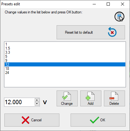
Control templates
You can use preconfigured templates (presets) to quickly set up the power supply.
Templates are lists of commonly used voltage and current values. Customize the lists according to your preferences and set the desired current parameters at the touch of a button (main window of the program, block "Control templates").
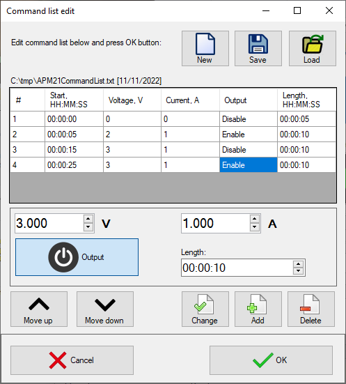
Command lists
To send a series of scheduled commands to the power supply, use the "List of commands" feature. Specify a sequence of commands consisting of specified values of voltage, current, output state and stage duration, save the resulting list to a file for further use and run it from the main program window ("Control List" block).
Customizable user interface
APM21 Pro allows to customize the user interface in a way that is convenient for you: hide and collapse all the blocks you don’t need with special buttons and leave only the ones you need.
History of events
APM21 Pro saves the history of events (displayed in the Protocol window) and measurement data (displayed on the graph in the main window) to a file. It is useful when you need to review power supply operation later.
Computer requirements
The computer used to operate the instrument must meet the following minimum requirements:
- 1 free USB port;
- installed operating system Windows XP or higher;
- .NET Framework 4.0 or higher installed.
Preparing the device for work
Hardware installation
To prepare for installation on the device, turn it off, connect the USB connector of the computer port to the corresponding connector of the controlled power supply using the A-B type USB cable.
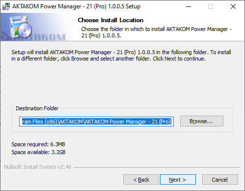
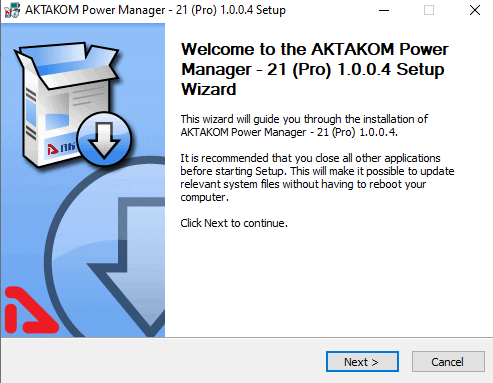
Software installation
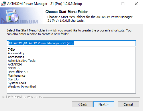
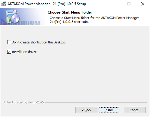
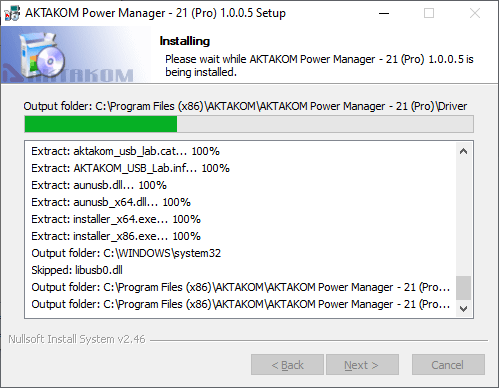
Find and run the installer and follow its instructions. At the end of the installation process, a program group will be created with shortcuts to the program and to the help system. You can launch them using the start menu. The USB interface driver must be installed before using the instrument. The files required for this will be placed in the working folder of the program in the Driver subfolder during the installation of the software, after which the installer will offer to install the driver automatically.
If you chose not to install the driver automatically, or if it failed for some reason, you can install the driver manually later. The driver installation procedure is described below.
Manual installation of the USB driver (for Windows 7)
Log in to Windows with administrator rights, connect the instrument to the computer.
Call the Control Panel from the Start menu, select the System item (or just press the Win + Pause key combination on the keyboard).
Click Device Manager. Find the AKTAKOM USB LAB device in it (it will be marked with a warning icon, since the driver for it has not yet been installed).
Open its properties (double-click), click the Update driver button.
Select "Search this computer for drivers" and then specify the location of the driver folder.
Choose to install the AKTAKOM USB Lab driver.
On the security warning, confirm your consent to install the driver.
Wait for the installation to finish.
At this point, the driver is ready to go.
Standard package
The software in the standard package of the device has no physical media (CD) and can be downloaded at www.tmatlantic.com after the purchasing and registering the equipment with a serial number.
We recommend you save a copy of your software. If lost: registered user can download software free of charge during warranty period. After warranty period has expired the software could be purchased and downloaded from the TM Atlantic website. The software could be written on the CD and shipped to the customer for an additional fee and only upon request.
Control via PC using Aktakom Power Manager 21 Professional
Controlling AKTAKOM power supplies via USB is convenient if the devices are at a short distance, for example, on the same table as the operator. If the distance is greater (in another room, laboratory, or even further away), it is convenient to use control via the LAN interface.
Upon first turning on the AKTAKOM Power Supplies, it is recommended to use USB interface control. This will allow you to set up network settings (used in your laboratory) for LAN interface application (see below).
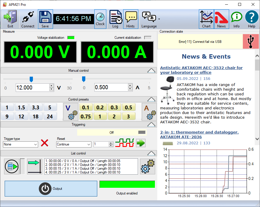
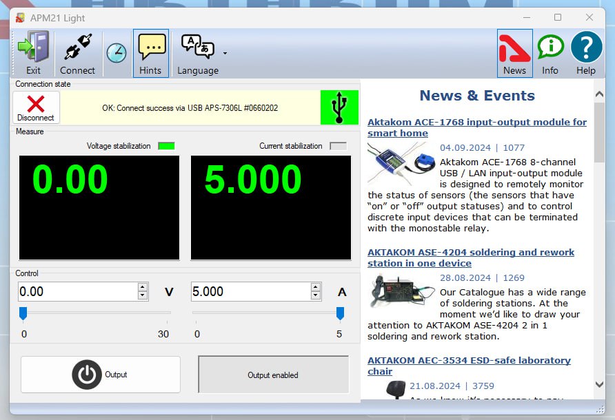
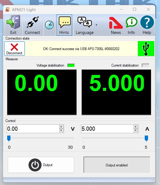
Main program window view:
Pic 1 Main program window view
You need to turn on the device and connect it to the computer using a USB cable (see Pic 2).
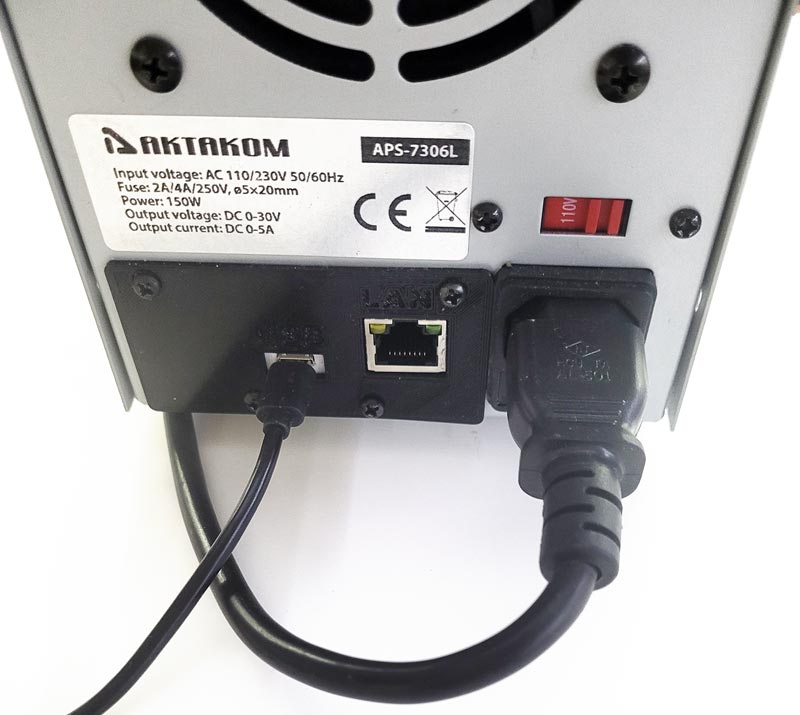
Pic 2 USB connection
When the application is running the Power Supply connection window will open (see Pic 3).
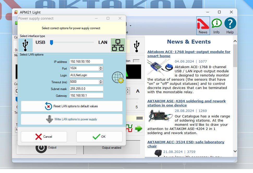
Pic 3 Connection window
In the connection window, simply click OK (with the interface switch set to USB), and the device will be automatically detected and connected. The device's name and serial number will be visible in the connection block. USB connection is complete, and you can now control the device. Manual control of the device (from the front panel) will be disabled. To return to manual control (from the front panel), you need to turn off the device using the power switch on the front panel (see Pic 4).
Pic 4 Connection block
After connecting the AKTAKOM power supply, the LED (on the top frame of the indicator) will blink red (this indicates USB remote control mode) (see Pic 5).
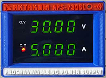
Pic 5 USB remote control mode
The voltage indicator shows a zero value (corresponding to the voltage at the output of the power supply), and this value will not change when entering or setting the output voltage value in the 'Control' block.
The voltage indicator will display the set output voltage value after pressing the 'Output' button.
The current indicator shows the set current value. This value will change when modifying or setting the output current value in the 'Control' block. This set value represents the current limit at which the AKTAKOM power supply will switch from CV (constant voltage) mode to CC (current limiting) mode. After pressing the 'Output' button, the current indicator will display the actual output current of the AKTAKOM Power Supply.
If you need to disable advertisements, you can click the AKTAKOM icon (see Pic 6).
Pic 6 Advertisements disabled
To configure the AKTAKOM power supply for LAN interface connection, you first need to set up the network parameters for the future LAN connection using a USB connection. To do this, in the 'Power supply connect' window (opened by clicking the 'Connect' button) (see Pic 7), you need to:
- Select the interface type as LAN (the background color of the window will change to green),
- Enter the network connection parameters used in your subnet (IP address (IPv4), Subnet mask, Gateway).
It is not recommended to change the Port parameter value.
The parameters visible in this window (including Login and Password) at the initial power-on of the device are the factory default settings. The network settings entered in the 'Power supply connect' window need to be saved to the AKTAKOM power supply by pressing the 'Write LAN option to Power supply' button. If you continue working via USB, there is no need to press the OK button.
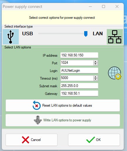
Pic 7 LAN remote control mode
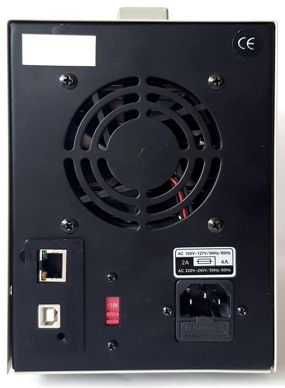
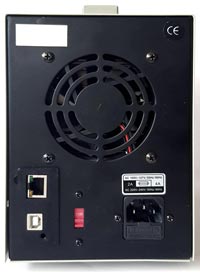
To connect the AKTAKOM power supply via the LAN interface (after entering the network settings as described earlier), you need to connect the LAN cable to the AKTAKOM power supply (Pic 8) and disconnect the USB cable from the PC.
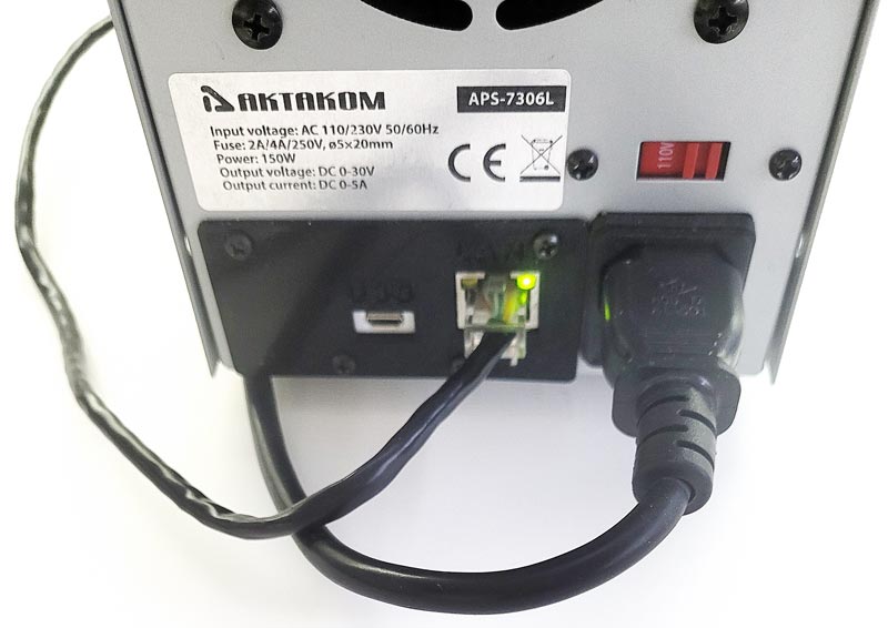
Pic 8 LAN connection
After connecting the AKTAKOM power supply to the LAN, you need to open the 'Power supply connect' window, check the correctness of the network settings (including Login and Password), and press the OK button. The connection status will be displayed in the main program window, in the 'Connection Status' block (Pic 9).
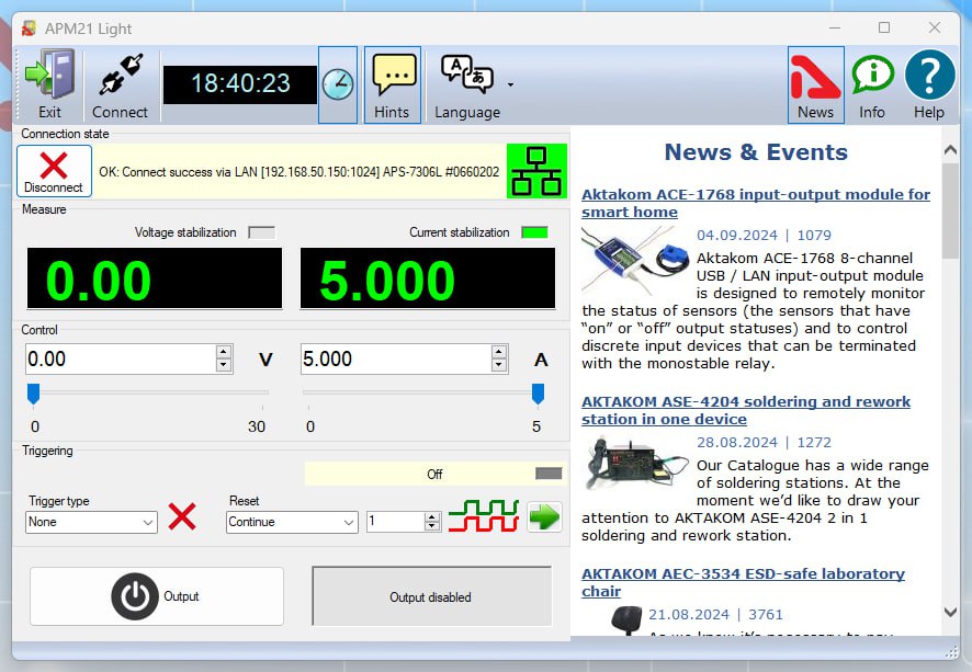
Pic 9 Main program window when connecting the AKTAKOM power supply via the LAN interface
Select the necessary interface type (USB or LAN), enter the settings for the network connection (IP address (IPv4), Subnet mask, Gateway) and press OK button to connect to the power supply. You will see the connection state in the main program window, "Connection state" block.
Pic 10 LAN remote control mode
In case of successful connection the program will remember the settings and next time it will try to use them to reconnect to the device.
To restore the connection break in the program operation click "Connect" button in the main window. Also use this window to record the network settings to the power supply memory. To do this open "Connection" window after the device connection via USB, enter the necessary settings in IP, port, login fields and click "Write LAN options to power supply." When recording you will need to enter a password (see Pic 11).
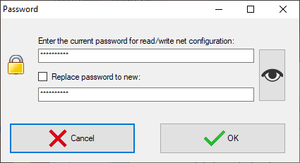
Pic 11 Password box
To change the password check box "Replace password to new".
After the device connection its current state will be displayed in Measurements block.
Las fuentes de alimentaciуn controladas de la serie AKTAKOM APS-XXXX estбn diseсadas para suministrar a los dispositivos inalбmbricos voltaje o corriente estabilizada durante los procesos de depuraciуn, reparaciуn e investigaciуn de laboratorio en tйrminos de clima templado.
El programa AKTAKOM Power Manager 21 Light estб diseсado para trabajar con uno de los siguientes modelos de fuente de alimentaciуn controlada:
- Fuente de alimentaciуn APS-7303L
- Fuente de alimentaciуn APS-1721 con opciуn LS
- Fuente de alimentaciуn APS-3610L
- Fuente de alimentaciуn APS-3103L
- Fuente de alimentaciуn APS-3310L
- Fuente de alimentaciуn APS-3605L
- Fuente de alimentaciуn APS-1721L
- Fuente de alimentaciуn APS-1602L
- Fuente de alimentaciуn APS-1503L
- Fuente de alimentaciуn APS-7305L
- Fuente de alimentaciуn de control remoto APS-7612L
- Fuente de alimentaciуn APS-3320L
- Fuente de alimentaciуn con control remoto APS-3605L con opciуn de sincronizaciуn externa (S)
- Fuente de alimentaciуn APS-3310L con opciуn de sincronizaciуn externa (S)
- Fuente de alimentaciуn con control remoto APS-3320L con opciуn de sincronizaciуn externa (S)
- Fuente de alimentaciуn con control remoto APS-3103L con opciуn de sincronizaciуn externa (S)
- Fuente de alimentaciуn con control remoto APS-3610L con opciуn de sincronizaciуn externa (S)
- Fuente de alimentaciуn de control remoto APS-7306L
- Fuente de alimentaciуn APS-7306LS con control remoto y sincronizaciуn externa
Requisitos del PC
La computadora utilizada para operar el instrumento debe cumplir con los siguientes requisitos mнnimos:
- 1 puerto USB libre;
- sistema operativo instalado Windows XP o superior;
- .NET Framework 4.0 o superior instalado.
Instalaciуn de hardware
Para instalar el dispositivo primeramente apбguelo, conecte el conector USB del ordenador al conector correspondiente de la fuente de alimentaciуn controlada mediante un cable USB A-B (Dibujo 1).
Dibujo 1
Busque y ejecute el instalador y siga sus instrucciones.
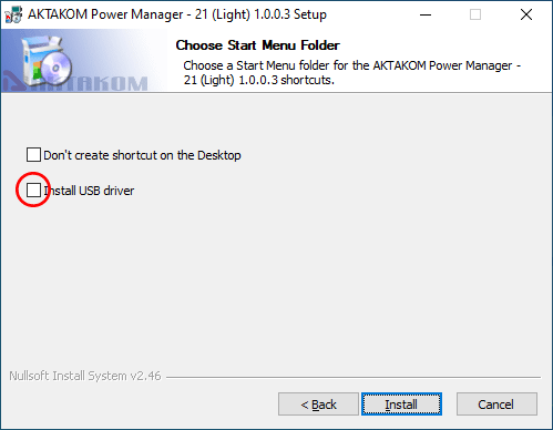
Al final del proceso de instalaciуn, se crearб un grupo de programas con accesos directos para el programa y para el sistema de ayuda. Puede iniciarlos usando el menъ de inicio. El controlador USB debe estar instalado antes de usar el instrumento. Al instalar el software, los archivos necesarios para esto se colocarбn en la carpeta de trabajo del programa en la subcarpeta Driver, luego de lo cual el instalador ofrecerб instalar el controlador automбticamente (Dibujo 2a).
Dibujo 2a
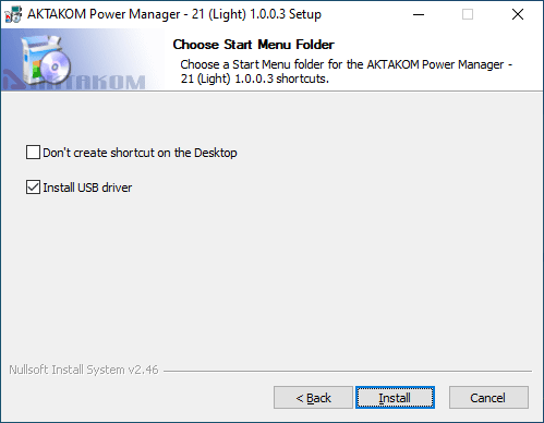
Nota: Si anteriormente habнa estado instalado el programa y por consiguiente el Driver, entonces no es necesario instalarlo de nuevo, no marcar la casilla (Dibujo 2b).
Dibujo 2b
Si se negу a instalar automбticamente el controlador o fallу por algъn motivo, puede instalarlo mбs tarde manualmente.
Descripciуn del trabajo con el programa
Ventana principal del programa (Dibujo 3):
Dibujo 3
Cuando se inicia la aplicaciуn, se abre el cuadro de diбlogo de conexiуn de la fuente de alimentaciуn (Dibujo 4):
Dibujo 4
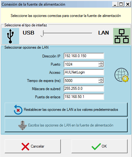
Seleccione el tipo de interfaz requerido (USB o LAN), ingrese la configuraciуn para la conexiуn de red (IP, puerto, inicio de sesiуn) y presione el botуn OK para conectarse a la fuente de alimentaciуn.
Verб el resultado de la conexiуn en la ventana principal del programa, en el bloque "Estado de la conexiуn".
Si la conexiуn es exitosa, el programa recordarб la configuraciуn y la prуxima vez que se inicie intentarб usarla para volver a conectarse automбticamente al dispositivo.
Para restaurar la conexiуn despuйs de una interrupciуn mientras el programa se estб ejecutando, haga clic en el botуn "Conectar" en la ventana principal. Utilice tambiйn este cuadro de diбlogo para escribir la configuraciуn de red en la memoria de la fuente de alimentaciуn. Para hacer esto, despuйs de conectarse al dispositivo a travйs de USB, abra el cuadro de diбlogo "Conexiуn", ingrese la configuraciуn requerida en los campos IP, puerto, inicio de sesiуn y haga clic en el botуn "Escribir configuraciуn LAN en la fuente de alimentaciуn". Al grabar, deberб ingresar una contraseсa (Dibujo 5).
Dibujo 5
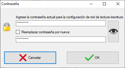
Utilice ANC Aktakom Net Configurator para cambiar la contraseсa y registrar configuraciones de red adicionales.
Despuйs de conectarse al dispositivo, su estado actual se mostrarб en el bloque de Medidas.
La tensiуn y la corriente de estabilizaciуn estбn controladas por los elementos de la Unidad de control. Encendido y apagado de la salida mediante el botуn Salir.
El bloque de Sincronizaciуn le permite utilizar las capacidades de entrada de sincronizaciуn para los modelos de instrumentos equipados con йl.
RESERVADOS TODOS LOS DERECHOS. El software AKTAKOM™ está protegido por leyes y tratados internacionales y federales sobre derechos de autor. Se prohíbe cualquier copia, reimpresión o uso no autorizado de este material. Ninguna parte de este software puede ser reproducida o transmitida de ninguna forma o por ningún medio, electrónico o mecánico, incluyendo fotocopias, grabaciones o por cualquier sistema de almacenamiento y recuperación de información sin el permiso expreso por escrito del autor / editor.
Windows, el logotipo de Windows son marcas comerciales registradas o marcas comerciales de Microsoft Corporation en los Estados Unidos y / o en otros países.
")