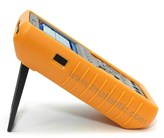
The popular handheld oscilloscope with widened bandwidth for signals research, their comparison on different channels and the electrical parameters measurement. Application: design and debug, circuit function test, education, technical training, maintenance testing.
Depending on a destination shipping cost may vary. Free shipping for orders over $450 on items weighting under 20 lbs (certain restrictions apply!) See shipping page for international rates or contact sales@tmatlantic.com
Sold out
Subscribe
Description
Specifications
Accessories
Application
FAQ
Software
Descripción
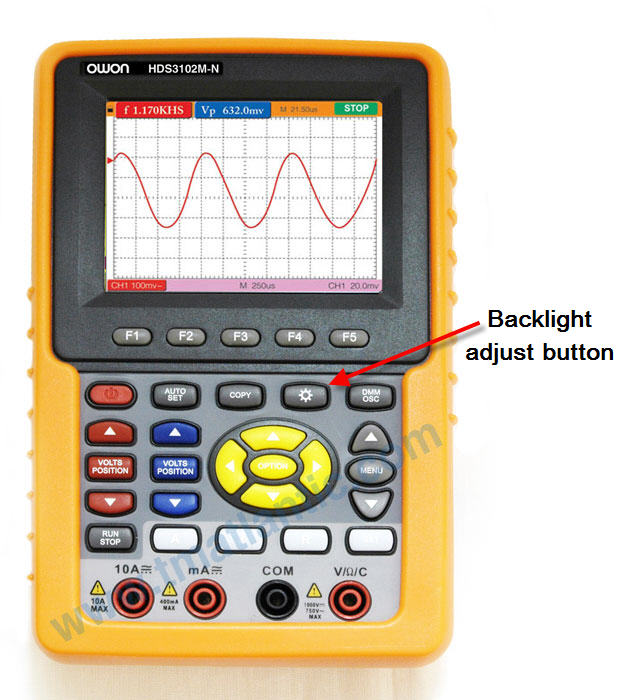
Classic Scopemeter (Digital storage oscilloscope + Digital Multimeter). DSO: Two channels; bandwidth 60MHz; sample rate (Real time) 250MSa/s; record length 6K points on each channel; cursor and automeasurement (20 types); trigger type: edge, video; Math; FFT; peak detect and average. DMM: 3¾ digits; VDC, VAC, DC, AC, resistance, capacitance, diode test, on-off test. Display: 3.8'' color LCD, TFT screen, 320×240 pixels. 110-220V; Dimensions: 7.1x4.5x1.6in/180x115x40mm. Weight: 22.8oz/645g
The oscilloscope should operate continuously for more than 30 minutes under the specified operating temperature.
If the operating temperature is up to or larger than 41°F/5°C, the system function menu must be opened to make the system perform a Auto-calibration procedure.
Except those specifications marked with the word Typical, all specifications can be up to the mentioned definitions.
Low frequency response (AD coupling, -3dB): ≥5Hz (at the BNC).
Rise time (typical one at the BNC):≤5.8ns
DC gain accuracy: ±3%
DC measurement accuracy (average value sampling mode):The voltage difference (ΔV) between any two points on the waveform after averaging the captured waveforms more than 16: ±(5% reading+0.05divisions)
Trigger
Trigger sensivity (Edge)
DC coupling 1div (DC~full bandwidth)
AC coupling Same as the DC coupling when it is equal to or larger than 50Hz
Triggering level range ±6 divisions from the screen center
Triggering level accuracy (typical) which is applicable to the signal with rise and fall time equal to or longer than 20ns ±0.3 divisions
Trigger displacement 655 divisions for pre-triggering and 4 divisions for post-triggering.
Trigger Holdoff range 100ns~10s
Make a 50% level setting (Typical). Operation with the input signal frequency equal to or larger than 50Hz.
Trigger sensitivity (Video triggering and typical mode) 2 divisions of peak-to-peak value
Signal system and line/field frequency (Video triggering mode); Support the NTSC, PAL and SECAM broadcasting systems of any field or line frequency
Probe
1X position
10X position
Bandwidth
Up to 6MHz (DC)
Up to full bandwidth (DC)
Attenuation rate
1:1
10:1
Compensation range
15pF~35pF
Input resistance
1MΩ±2%
10MΩ±2%
Input impedance
85pF~115pF
14.5pF~17.5pF
Input voltage
<200VDC+Peak AC
<600VDC+Peak AC
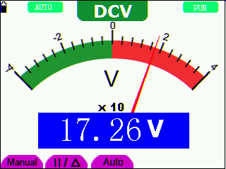
Voltage (VDC) Input Impedance: 10MΩ. Max. Input Voltage: 1000V (DC or AC peak-to-peak value)
Range
Accuracy
Resolution
400.0mv
±1%±2digit
100µV
4.000V
1mV
40.00V
10mV
400.0V
100mV
1000.0V
1V
Voltage (VAC) Input Impedance: 10MΩ. Max. Input Voltage: 750V (AC, virtual value). Frequency range: from 40Hz to 400Hz. Display: Virtual value of the sine wave
Range
Accuracy
Resolution
4.000V
±1%±3digits
1mV
40.00V
10mV
400.0V
100mV
750.0V
±1.5%±3digit
1V
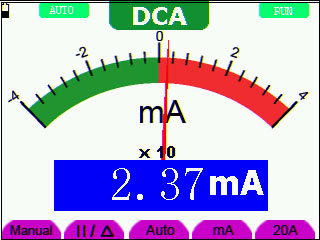
Direct Current (DC)
Range
Accuracy
Resolution
40.00mA
±1.5%±1digit
10µA
400.0mA
±1.5%±1digit
100µA
10A
±3%±3digit
10mA
Alternating Current (AC)
Range
Accuracy
Resolution
40.00mA
±1.5%±3digit
10µA
400.0mA
±2%±1digit
100µA
10A
±5%±3digit
10mA
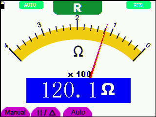
Resistance
Range
Accuracy
Resolution
400.0Ω
±1%±3digit
0.1Ω
4.000kΩ
±1%±1digit
1Ω
40.00kΩ
10Ω
400.0kΩ
100Ω
4.000MΩ
1kΩ
40.000MΩ
±1.5%±3digit
10kΩ
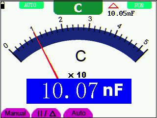
Capacitance
Range
Accuracy
Resolution
51.20nF
±3%±3digit
10pF
512.0nF
100pF
5.120µF
1nF
51.20µF
10nF
100µF
100nF
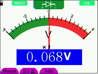
Diode
Voltage reading: 0 V~1.5 V
On-off Test
There is a beep sound when the on-resistance is less than 50Ω.
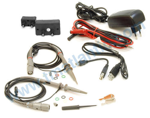
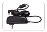
1. Power adapter
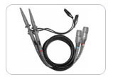
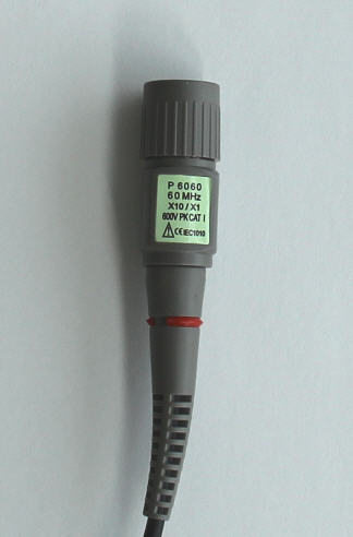
2. Oscilloscope Probe x 1 (grey)
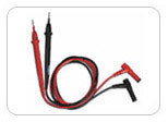
3. Multimeter test lead x 2 (black and red)
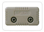
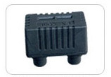
4. Extension module for big current measurement
5. Module for small capacitance measurement
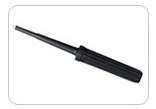
6. Probe adjustment tools
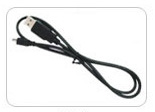
7. USB communication cable
8. User Manual
9. CD-ROM (software)
10. Soft carrying case
The use of oscilloscopes-multimeters
Multimeter mode
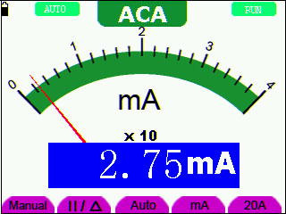
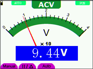
AC Current Measurement AC Voltage Measurement
DC Current Measurement DC Voltage Measurement
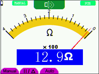
Resistance Measurement Relative Measurement
On off Test Diode Measurement
Capacitance Measurement
Oscilloscope mode
Autoscale Horizontal - Vertical multi period waveforms1 Autoscale Horizontal - Vertical multi period waveforms2
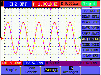
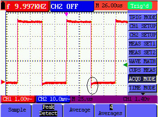
Automatic Scope Measurements Average Factor Sampling Mode
Peak Detection Persistence to Observe Dynamic Signals
High voltage measurement testing are not allowed over 300 volts
Even when you can read in a probe 600V PK CAT I. The Aktakom, Owon or Rigol oscilloscopes does not support more than 300V RMS or 400V PK. For higher voltage please contact us to request a special device.
The measured voltage amplitude value is 10 times greater or smaller than the actual value
Check whether the channel attenuation coefficient and the attenuation coefficient of the probe used is match. Up
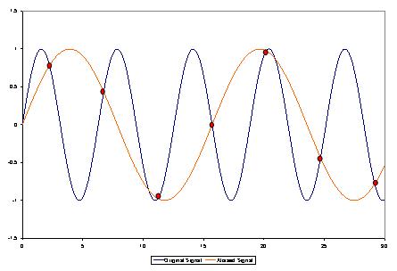
When changing the horizontal sweep on the digital oscilloscope at different horizontal points observed inexplicable change in the form of the same signal, why is this happening?
In fact, this is not a problem.
Just keep in mind that you're using a digital oscilloscope, which digitizes the signal with different sampling rates depending on the selected horizontal sweep, and then connects the digitized points with strait line while restoring the real shape of the signal.
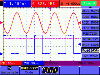
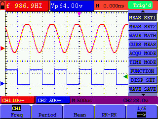
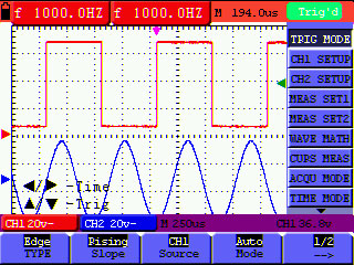
Your first screen shows that you are measuring voltage 50 Hz with the 10 ms / div sweep and a sampling frequency of 20 kHz Ks/s
One signal period (20 ms), digitized in this mode, 20E-03 (sec) * 20E03 (1/sec) = 400 points. This is enough to properly restore and interpolate a sine wave of 50 Hz (i.e. in a period of 20 ms).
Normal display, with a sweep 10 ms / div:
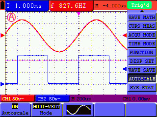
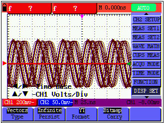
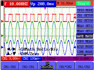
Distortion of the same signal at 10 s / div sweep
Your second screen is set to sweep 10 sec / div, and sample rate on a sweep turned to 20 samples per second (20 Sa / s). I.e. one signal period 20 ms had: 20E-03 (sec) * 20 (1/sec) = 0.4 points. That means that to restore (to interpolate the points) a sine wave with less than one point in time is impossible, so you get this mess (known as "aliasing" or a false frequency) formed by the beats of the measured frequency and sampling frequency.
In order to correctly install a data collection in a digital oscilloscope one should follow a simple rule - the sampling rate must be at least 5-10 times higher than the frequency signal, in that case you will not have the issues that we just discussed.
This applies to all digital oscilloscopes and in no way connected to any particular make or model of oscilloscope or its probes.
There is wave form displayed, but it is not stable
Check whether the Source item in the TRIG MODE menu is in conformity with the signal channel used in the practical application.
Check on the trigger Type item: The common signal chooses the Edge trigger mode for Type and the video signal the Video. Only if a proper trigger mode is applied, the wave form can be displayed steadily.
Try to change the trigger coupling into the high frequency suppress and the low frequency suppress to smooth the high frequency or low frequency noise triggered by the interference.
Escopiometro clásico: Osciloscopio digital con almacenamiento (DSO) + Multímetro Digital (DMM).
DSO: Dos canales. Ancho de banda de 60 MHz. Frecuencia de muestreo (en tiempo real) de 250MS/s. Máxima longitud de registro 6 mil puntos por cada canal. Veinte mediciones automáticas. Disparador de borde, de video y matemático. FFT. Detección de picos y promedio.
DMM: 3 ¾ dígitos, VCD, VCA, CC, AC, resistencia, capacitancia, testeo de diodos, de encendido y apagado.
Monitor LCD de 3.8'' a color, pantalla TFT de 320 × 240 píxeles. Dimensiones: 7.1” x 4.5” x 1.6” / 180mm x 115mm x 40mm. Peso: 22.8 oz / 645 g.