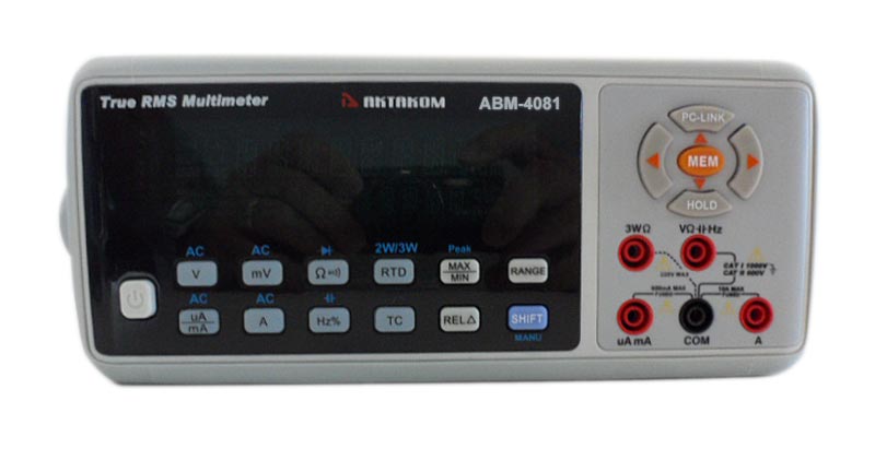
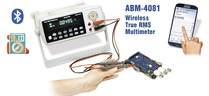
Multipurpose benchtop digital multimeter
- Dual VFD display, 60000 counts
- True RMS
- Bluetooth
- Duty cycle
- Diod test
- Continuity test
- Backlit display
- Auto turn-off
- Data hold
- Auto and manual measurement range selection
- MIN/MAX/HOLD/REL
- SD card or USB
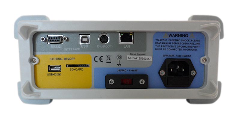
- USB Interface host/device, RS-232
| DC Voltage (DCV) | 1000 V |
| DCV Accuracy | ±0.02% |
| AC Voltage (ACV) | 1000 V |
| ACV Accuracy | ±0.8% |
| DC Current (DCA) | 10 A |
| DCA Accuracy | ±0.2% |
| AC Current (ACA) | 10 A |
| ACA Accuracy | ±0.75% |
| Frequency | 10 Hz...6 MHz |
| Resistance | 600 Ω...60 MΩ |
| Capacitance | 6 nF...60 mF |
| Temperature | -200 °C...1200 °C |
| Temperature sensor type | Type K thermocouple, Type J thermocouple, Type E thermocouple, Type N thermocouple, Type T thermocouple, Type B thermocouple, Type R thermocouple, Type S thermocouple, PT100, PT500, PT1000, CU50, NI120 |
| Diode test | + |
| Continuity check | + |
| True RMS | + |
| Autorange | + |
| Data hold | + |
| Min/Max measurement | + |
| Relative measurement | + |
| Special features | SD card |
| Interface | USB Host, USB Device, LAN, RS-232, Bluetooth |
| Display | VFD, 60000 counts |
| Power supply | 100...240 VAC |
| Dimensions | 13.8 x 9.4 x 3.9 in / 350 x 240 x 100 mm |
Specifications
|
Function
|
Range
|
Basic Accuracy
|
|
Voltage DC
|
600.00mV / 6.0000V / 60.000V / 600.00V / 1000.0V
|
±0.02%
|
|
Voltage AC
|
600.00mV / 6.0000V / 60.000V / 600.00V / 1000.0V
|
±0.8%
|
|
Current DC
|
60.000μA / 600.00μA / 60.00mA / 600.00mA / 10.000A
|
±0.2%
|
|
Current AC
|
60.000μA / 600.00μA / 60.00mA / 600.00mA / 10.000A
|
±0.75%
|
|
Resistance
|
600.00 / 6.0000k / 60.000k / 600.00k / 6.0000M / 60.000MΩ
|
±0.3%
|
|
Frequency
|
10.000Hz … 6.0000MHz
|
±0.01%
|
|
Capacitance
|
6.0000nF / 60.000nF / 600.00nF / 6.0000μF / 60.000μF / 600.00μF / 6.0000mF / 60.000mF
|
±3.0%
|
|
Thermocouple Temperature
|
-200°C…1200°C K / J / T / E / R / S / B / N
|
|
RTD Temperature
|
-200°C…600°C PT100 / PT500 / PT1000 / Cu50 / Ni120
|
|
Memory
|
16000 point internal / USB disk or SD card external
|
- Dual VFD display, 60000 counts
- True RMS
- Bluetooth
- Duty cycle
- Diod test
- Continuity test
- Backlit display
- Auto turn-off
- Data hold
- Auto and manual measurement range selection
- MIN/MAX/HOLD/REL
- SD card or USB
- USB Interface host/device, RS-232
- Dimensions: 13.8x9.4x3.9in / 350x240x100mm
- Weight: 2.5kg/5.5lb
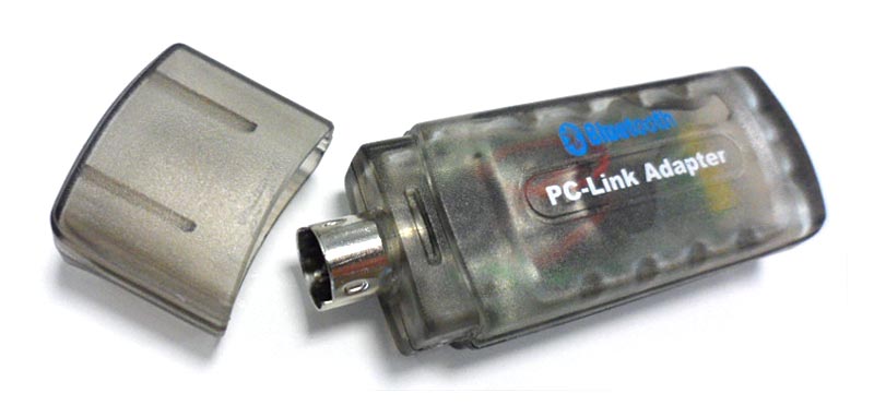
The software in the standard package of the device has no physical media (CD) and can be downloaded at www.tmatlantic.com after the purchasing and registering the equipment with a serial number. This software is paid-for and its cost is included into device value. In the new version of the software, when connecting the unit for the first time, it will ask for a license (access key). It is available online after product registration. Insert the entire character set by coping and pasting it from www.tmatlantic.com. Follow the instructions on the site. We recommend that you make and keep a copy of the downloaded software. Follow our websites news releases to receive software updates.
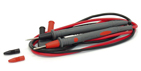
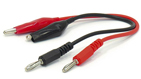
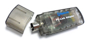
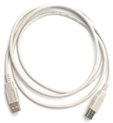
OPTIONAL ACCESSORIES:
Recording your Software on CD
ABM-4081 applications
ACV/Hz Measurement
The voltage measurement range is of AC 0.0001V∼1000V and the measurement method is as follows:
- Turn on the power and press the SHIFT button and after V button.
- Insert the red and black testing lines into VΩHz end and COM end respectively.
- Connect the meter to the two ends of the measured voltage with the red and black probes.
- Read the meter’s data from the main display area, and read the signal’s frequency on the secondary display area. When OL displaying on the meter, it indicates the measured voltage exceeding the meter’s range and it is necessary to remove both the red and black probes from the measured circuit immediately. The Voltage frequency can be measured fewer than 60kHz.
- By pressing the RANGE key it is possible to select range manually. While displaying OL during manual range measurement, it is necessary to select a larger range. When OL displaying under the maximum range, it indicates the voltage exceeding 1000V, so it is necessary to remove both the red and black probes from the measured circuit immediately.
Notes: in case of probe hanging in the air, the voltage inducted by the testing line may cause unstable readings on the display screen, but that will not affect the accuracy of measurement.
 Warning: Not try to measure a voltage higher than 1000V Warning: Not try to measure a voltage higher than 1000V
DCV Measurement
The voltage measurement range is of AC 0.0001V∼1000.0V and the measurement method is as follows:
- Turn on the power and press the V button.
- Insert the red and black testing lines into VΩHz end and COM end respectively.
- Connect the meter to the two ends of the measured voltage with the red and black probes.
- Read the meter’s data from the main display area, When OL displaying on the meter, it indicates the measured voltage exceeding the meter’s range and it is necessary to remove both the red and black probes from the measured circuit immediately.
- By pressing the RANGE key it is possible to select range manually. While displaying OL during manual range measurement, it is necessary to select a larger range. When OL displaying under the maximum range, it indicates the voltage exceeding 1000V, so it is necessary to remove both the red and black probes from the measured circuit immediately.
Notes: in case of probe hanging in the air, the voltage inducted by the testing line may cause unstable readings on the display screen, but that will not affect the accuracy of measurement.
Warning: Not try to measure a voltage higher than 1000V
DC mV/AC mV Measurement
The DC voltage measurement range is 1μV∼600mV but AC voltage range is 0.01mV∼500mV, the method is as follows:
- Turn on the power switch and press mV key to enter the DC mV mode. (SHIFT+mV =AC mV)
- Insert the red testing line into the VΩHz end and the black testing line into the COM end.
- When performing DCmV measurement, connect the red probe to the positive polarity of the measured voltage and the black probe to its negative polarity. While performing AC mV measurement, it will be done by connecting the red probe and the black probe into the two ends of the measured voltage.
- Read the measured value from the main display area. If performing AC mV measurement, the secondary display area is the signal’s frequency. If OL displaying on the main display area, it indicates the measured voltage exceeding the range of the meter and it is necessary to remove both the red and black probes from the measured circuit immediately.
- When performing DC mV measurement, by pressing the RANGE key it is possible to select range manually. If OL displaying during manual range measurement, it is necessary to select a larger range. If OL displaying under the maximum range, it is necessary to remove both the red and black probes from the measured circuit immediately. When performing AC mV measurement manual range, press the RANGE key is void.
Notes: In case of probe hanging in the air, the voltage inducted by the testing line may cause unstable readings on the display screen, but that will not affect the accuracy of measurement.
Warning: Estimate the Voltage before measurement, not to exceed 220V rms.
RTD Measurement
The RTD measurement range as blew table, the methods is as follows:
| Type | 385 TYPE | 392 TYPE |
| Resolution |
| MAX | MIN | MAX | MIN | MAX | MIN | 0.1 °C |
| PT100 / PT500 / PT1000 | 800 °C | -200 °C | 660 °C | -200 °C |
|
| 0.1 °C |
| CU50 |
|
|
|
| 150 | -50 | 0.1 °C |
| NI120 |
|
|
|
| 260 | -80 | 0.1 °C |
- Turn on the power switch and press the RTD key to switch the type of the RTD. There are eight type RTD for you to choose. 385 or 392 type you can set it on the menu setting. Two-line or three-line switch press SHIFT + RTD.
- if select 2-wire measure, insert the red testing line into the VΩHz end and the black testing line into the COM end. If select 3-wire measure, source terminal is use to 3WΩ end, VΩHz is test end and COM is common end.
- When performing RTD measurement, connect the red and black probes to the two ends of RTD and read the temperature value from the main display screen. The secondary display area should be showing the RTD type and the 2-wire or 3-wire information.
- Read the temperature value from the main display area. If OL displaying on the main display area, it indicates the measured temperature exceeding the range of the meter or connect is unstable and it is necessary to remove the RTD from the measured environment.
- When performing RTD measurement manual range, press the RANGE key is void.
Notes: In case of probe hanging in the air, the main display area will display OL. What kind of the RTD you used, you should choose this type on the meter to measure. Press the RTD key to switch the RTD type.
TC Measurement
The thermocouple (TC) measurement range as blew table, the methods is as follows:
|
TC name
|
Minimum test temperature
|
Maximum test temperature
|
Resolution
|
|
TCK
|
-200°C / -328°F
|
1370°C / 2498°F
|
0.1°C/°F
|
|
TCJ
|
-200°C / -328°F
|
1030°C / 18868°F
|
0.1°C/°F
|
|
TCE
|
-200°C / -328°F
|
780°C / 14368°F
|
0.1°C/°F
|
|
TCN
|
-200°C / -328°F
|
1300°C / 23728°F
|
0.1°C/°F
|
|
TCT
|
-200°C / -328°F
|
400°C / 7528°F
|
0.1°C/°F
|
|
TCB
|
600°C / 1112°F
|
1800°C / 32728°F
|
1°C/°F
|
|
TCR
|
-50°C / -58°F
|
1750°C / 31828°F
|
1°C/°F
|
|
TCS
|
-20°C / -4°F
|
1750°C / 31828°F
|
1°C/°F
|
- Turn on the power switch and press the TC key to switch the type of the thermocouple. There are eight type of thermocouple for your choose.
- Insert the positive terminal into the VΩHz end and the negative terminal into the COM end.
- When performing TC measurement, connect the red probe to the positive polarity of the measured thermocouple and the black probe to its negative polarity.
- Read the measured value from the main display area, the room temperature on the secondary display area. If OL displaying on the main display area, it indicates the measured temperature exceeding the range of the meter or connect is unstable and it is necessary to remove the thermocouple from the measured environment.
- When performing thermocouple measurement manual range, press the RANGE key is void.
Notes: In case of probe hanging in the air, the main display area will display OL. What kind of the thermocouple you used, you should choose this type on the meter to measure. Press the TC key to switch the thermocouple.
The second display view will show the ambient temp.
Frequently Asked Questions
How to measure capacitance using ABM-4081 multimeter?
How to measure DC μA/mA or AC µA/mA using ABM-4081 multimeter?
How to measure maximum and minimum values using ABM-4081 multimeter?
How to measure (logic) frequency and duty ratio using ABM-4081 multimeter?
How to measure DC Ampere/AC Ampere using ABM-4081 multimeter?
How to measure resistance, continuity, diode using ABM-4081 multimeter?
How to measure peak value using ABM-4081 multimeter?
How to measure capacitance using ABM-4081 multimeter?
|
|
The measurement range of capacitance is of 0.1pF~60mF and the measurement methods are as follows:
- Turn on the power switch and press SHIFT + Hz% button.
- Insert the red and black testing lines into the VΩHz input end and the COM input end respectively.
- If exists voltage in the capacitor, connect the two ends of the capacitor for a short time to discharge.
- Connect the red and black probes to the two ends of the capacitor, if the measured capacitor is heteropolar, it is necessary to connect the red probe to the positive polarity of the capacitor and the black probe to its negative polarity.
- Read the capacitance from the display screen. While displaying OL during manual range measurement, it is necessary to select a larger range. When OL displaying under the maximum range, it indicates the capacitance value > 63mF, then meter will display OL, while capacitance value < 0.1pF, it will display zero.
- It is possible to select range manually by pressing the RANGE key.
Notes: When performing measurement on 600μF...63000μF capacitor, in order to ensure measurement accuracy the meter takes a relative long time to discharge capacitor, so it is relatively slow in refreshing the measured value. In addition, not to perform Capacitance measurement on a circuit board on which there are other parallel devices, for that may leads to very large error.
Up
|
How to measure DC μA/mA or AC µA/mA using ABM-4081 multimeter?
|
|
The measurement range of DC/AC current is 0.01μA~6000µA and the measurement methods are as follows:
- Turn on the power switch and press μA/mA button (SHIFT +μA/mA=AC μA/mA).
- Repeat step 1, may change the µA to mA.
- Insert the red testing line into the mA/μA input end and the black testing line into the COM input end.
- Turn off the power of the measured circuit, connect the red and black probes to the measured circuit in serial way and then turn on the power of the measured circuit.
- Read the measured value from the main display area. If it displays as positive during the DC measurement, it means the current is flowing into the meter from the red testing line, while it displaying as negative, it means the current is flowing into the meter from the black testing line. If it displays as OL, it means current exceeding range. When performance AC µA/µA measurement, the secondary display area is the signal’s frequency. While displaying OL during manual range measurement, it is necessary to select a larger range. When OL displaying under the maximum range, it indicates the resistor is larger than 600mA/6000µA.
Warning: Estimate the current before measurement, not to exceed 0.63A current of the fuse.
Up
|
How to measure maximum and minimum values using ABM-4081 multimeter?
|
|
Pressing the MAX/MIN key the meter will enter the maximum value, minimum value record state and display the maximum value on the second display zone. The meter measures the present value and continuously judges if it is necessary to update the maximum or minimum value. Pressing the MAX/MIN key again it is possible to select displaying the minimum value. Under the maximum and minimum value record state, press the MAX/MIN key for two seconds and then release it, the meter will exit the MAX/MIN record state.
Up
|
How to measure (logic) frequency and duty ratio using ABM-4081 multimeter?
|
|
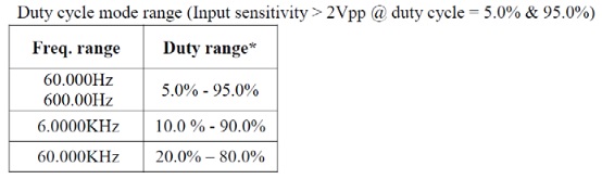
The frequency range is 4Hz~60MHz, while the duty ratio measurement range and method are as follows:
- Turn on the power switch and press Hz% button.
- Insert the red testing line into the VΩHz end and the black testing line into the COM end.
- Connect the red testing line to high logic level, the black one to low logic level.
- Read the measured value from the main display area. The secondary display area is the signal’s duty cycle. If the frequency of the measured signal is lower than the meter’s measurement range, the reading will be displayed as zero.
- By pressing the RANGE key it is possible to select range manually. While displaying OL during manual range measurement, it is necessary to select a larger range. When OL displaying under the maximum range, it indicates the frequency exceeding 60MHz, so it is necessary to remove both the red and black probes from the measured circuit immediately.
Notice: Duty measurement can not be measured over 60.000kHz.
Up
|
How to measure DC Ampere/AC Ampere using ABM-4081 multimeter?
|
|
The measurement range of DC current is 0.1mA~10A, and the measurement methods are as follows:
- Turn on the power switch and press A button. (SHIFT + A =AC Ampere)
- Insert the red testing line into the A input end and the black testing line into the COM input end.
- Turn off the power of the measured circuit, connect the red and black probes to the measured circuit in a serial way and then turn on the power of the measured circuit again.
- Read the measured value from the main display area. During the DC measurement, if it displays as positive, it means the current is flowing into the meter from the red testing line, while it displays as negative, it means the current is flowing into the meter from the black testing line. During the AC measurement the secondary display area is the signal’s frequency. While displaying OL during manual range measurement, it is necessary to select a larger range. When OL displaying under the maximum range, it indicates the current is larger than 10A.
Warning: Estimate the current before measurement, not to exceed 11A current of the fuse
Up
|
How to measure resistance, continuity, diode using ABM-4081 multimeter?
|
|
The measurement range of diode is of 0~2.2V.
The measurement range of resistance is of 0~60MΩ.
The measurement range of continuity is of 0~600Ω.
The measurement methods are as follows:
- Turn on the power switch and press Ω
 to switching Resistance/Continuity/Diode. to switching Resistance/Continuity/Diode.
- Insert the red testing line into the VΩHz end and the black testing line into the COM end.
- For the resistance measurement, connect the red and black probes to the two ends of resistor and read the resistance value from the main display area. While displaying OL during manual range measurement, it is necessary to select a larger range. When OL displaying under the maximum range, it indicates the resistor is larger than 60MΩ. As for the continuity measurement, connect the red and black probes to the two measured points respectively. In case of the resistance between the two points being less than about 50Ω~60Ω, the buzzer will sound while the display screen displaying the value of resistance. If OL displaying, it indicates the resistance between the two points is larger than 600Ω. As for the Diode measurement connect the red probe to the positive polarity of the diode and the black probe to its negative polarity, while the display screen will display the forward voltage drop. Connect the black probe to the positive polarity of the diode and the red probe to its negative polarity, if OL displaying on the display screen, it indicates the backward resistance of the diode being normal, while OL not displaying, it indicates that the drop of diode.
Notes: In case of performing diode/resistance/continuity test on circuit board, it is necessary firstly to turn off the power of the circuit board and then perform the measurement. As there may be other parallel circuits, so the displayed value of test is not surely the results listed in items 3.
Up
|
How to measure peak value using ABM-4081 multimeter?
|
|
Press the SHIFT + MAX/MIN the meter will enter the peak mode. The meter provides a peak hold function to capture the real peak value for voltage or current measurement mode. In a case of a 1V sine wave input voltage, the peak hold function gets a maximum peak value of 1.414V and minimum peak value of -1.414V ideally. Press SHIFT + MAX/MIN under the peak mode to exit the peak mode. Peak mode is unavailable, when at the DCmV / AC mV / OHM / DIODE / CONT / RTD / TC / frequency / capacitance measurement.
Up
|
Multímetro multipropósito
- Pantalla doble VFD, 60000 cuentas
- True RMS
- Bluetooth
- Ciclos de trabajo
- Prueba de Diodo
- Prueba de continuidad
- Pantalla retroiluminada
- Auto apagado
- Retencion de datos
- Selección manual y automática del rango de medición
- MIN/MAX/HOLD/REL
- Tarjeta SD o USB
- Interfaz USB host/device y RS-232
Back to the section
|